Solar power plant

a solar power plant and tracking technology, applied in the direction of pv power plants, lighting and heating apparatus, heat collector mounting/support, etc., can solve the problems of power generation technology, high cost of solar power generation technology compared to commercial power, and variability in the amount of energy generated, so as to facilitate the altitude adjustment northwards and increase the focusing efficiency of photovoltaic modules

Inactive Publication Date: 2010-08-05
CITY ENVIRONMENT ENG
View PDF18 Cites 28 Cited by
  • Summary
  • Abstract
  • Description
  • Claims
  • Application Information

AI Technical Summary

Benefits of technology

The present invention is a solar power plant that uses a solar tracking apparatus to increase the efficiency of photovoltaic modules. The plant can track the sun both westward and northward to adjust for altitude. This results in more sunlight being captured and converted into energy.

Problems solved by technology

The technical problem addressed in this patent text is the inaccurate positioning and complex structure of conventional solar tracking apparatus, which makes it difficult to simultaneously drive various photovoltaic modules along the sun.

Method used


Image

  • Solar power plant
  • Solar power plant
  • Solar power plant

Examples


Embodiment Construction

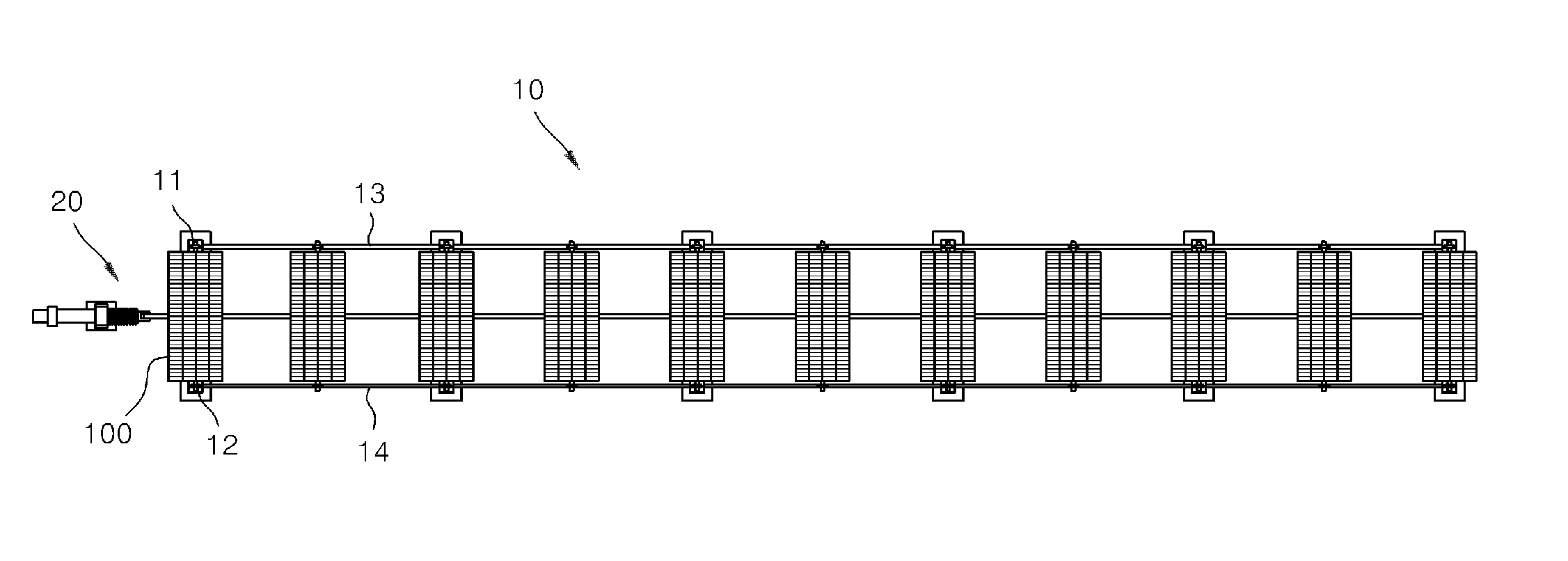
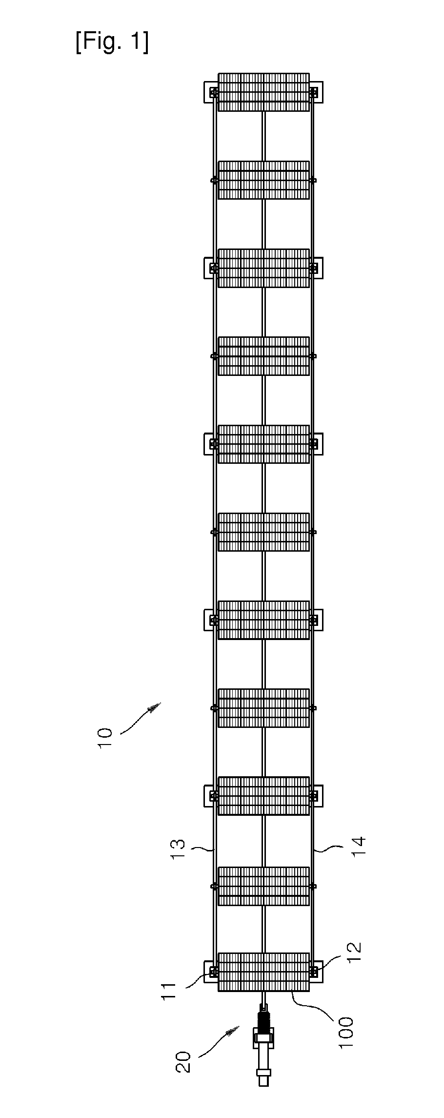
[0030]The solar power plant according to the present invention tracks the diurnal motion of the sun from the east to the west and adjusts its altitude with respect to the sun, thereby generating the electricity. The solar power plant according to an embodiment of the present invention is shown in FIGS. 1 through 6.

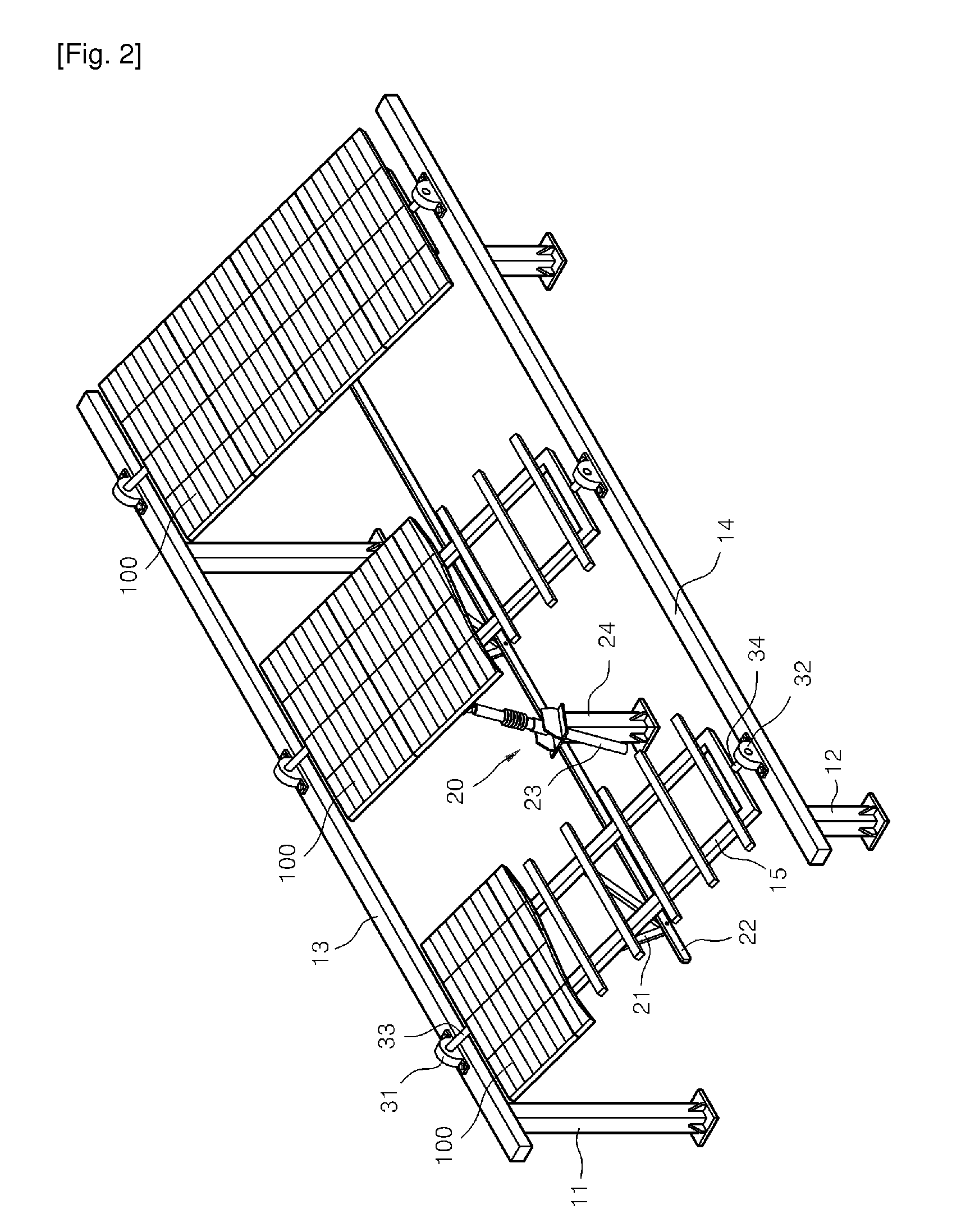
[0031]Referring to FIGS. 1 through 6, the solar power plant 10 includes first and second support members 11 and 12 installed on the ground, slant land, or a building and having the same or different heights, main frames 13 and 14 hinged to the respective first and second support members 11 and 12, sub frames 15 installed in a direction parallel to the main frames 13 and 14, for example, northwards, photovoltaic modules 100 installed on the respective sub frames 15, and rotating means 20 simultaneously rotating the sub frames 15 having the photovoltaic modules 100.

[0032]When installing the sub frames 15 for the main frames 13 and 14, first and second pillow blocks 31 and 32...


PUM


Abstract

A solar power plant is provided. The solar power plant includes a plurality of first support members positioned in the front end of the solar power plant, main frames hinged to the respective first support members, a plurality of second support members positioned in the rear ends of the main frames, a plurality of sub frames rotatably installed on the main frames and arranged in parallel with one another, photovoltaic modules installed on the respective sub frames, and rotating means simultaneously rotating the sub frames with respect to the main frames by a predetermined angle in forward and reverse directions.

Description


Claims


Application Information

Patent Timeline
Owner CITY ENVIRONMENT ENG
Why Eureka
Try Eureka