
Thrombolysis Catheter

a thrombolysis catheter and catheter technology, applied in the field of thrombolysis catheters, can solve the problems of stroke, even death, and the hinderance of local thrombolysis procedures, and achieve the effect of reducing the stress placed on the surrounding blood vessel(s)

Inactive Publication Date: 2010-07-29
BOSTON SCI SCIMED INC
View PDF5 Cites 5 Cited by
  • Summary
  • Abstract
  • Description
  • Claims
  • Application Information

AI Technical Summary

Benefits of technology

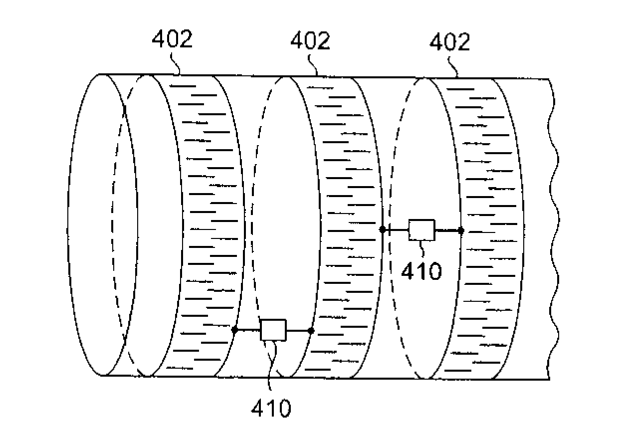
[0019]One advantage of the present invention is that a thrombolysis catheter apparatus can be provided in which the shape of the thrombolysis catheter portion is controlled along a substantial portion of its length. This allows the thrombolysis catheter portion to be efficiently advanced through complex anatomical structures, including hard-to-reach locations in the neurovasculature, allowing thrombolysis procedures to be conducted that would otherwise not be feasible.
[0020]Moreover, by controlling the electroactive polymer actuators to impart an orientation to the thrombolysis catheter that is complementary to the three-dimensional spatial trajectory of the blood vessel(s) through which the thrombolysis catheter portion is advanced, the stresses that are placed on the surrounding blood vessel(s) are reduced. This in turn reduces the probability that emboli will be dislodged, for example, from atheroma that are commonly present in cranial blood vessels.

Problems solved by technology

The occlusion can arise, for example, from a blood clot or embolus becoming lodged in one of the small arteries of the brain, and can lead to stroke, or even death, if left untreated.
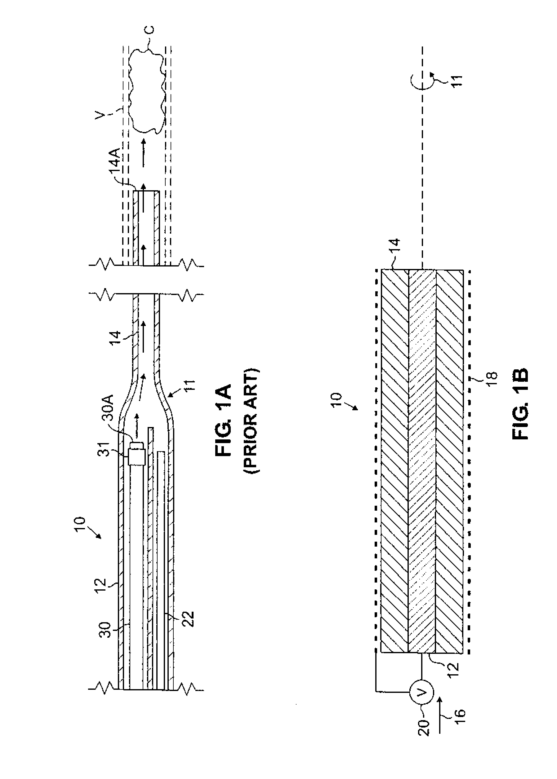
Unfortunately, localized thrombolysis procedures are presently hindered by the difficulties that are encountered in steering thrombolysis catheters like that described above through the vasculature, particularly the tortuous blood vessels of the neck and head, to the site of the occlusion.
Because time is of the essence where occlusions of the neurovasculature are concerned, these difficulties have presented a major obstacle in the widespread acceptance of thrombolysis catheters in the treatment of occlusive stroke.

Method used


Image

  • Thrombolysis Catheter
  • Thrombolysis Catheter
  • Thrombolysis Catheter

Examples


Embodiment Construction

[0035]The present invention now will be described more fully hereinafter with reference to the accompanying drawings, in which several embodiments of the present invention are shown. This invention may, however, be embodied in different forms and should not be construed as limited to the embodiments set forth herein.

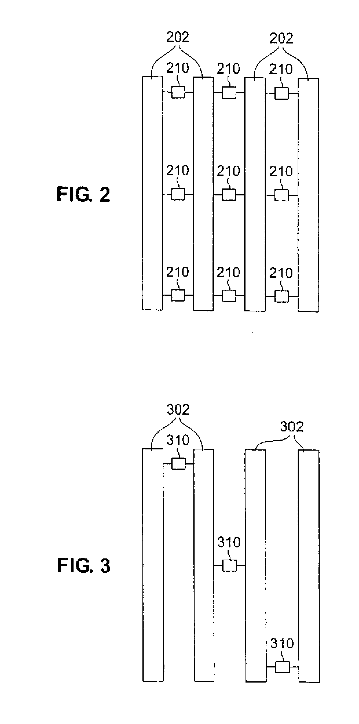
[0036]In many embodiments of the present invention, a thrombolysis catheter is provided in which electroactive polymer actuators are integrated into the thrombolysis catheter structure.

[0037]Actuators based on electroactive polymers are preferred for the practice of the present invention due to their small size, large force and strain, low cost and ease of integration into the thrombolysis catheters of the present invention.

[0038]Electroactive polymers, members of the family of plastics referred to as “conducting polymers,” are a class of polymers characterized by their ability to change shape in response to electrical stimulation. They typically structurally feature a c...


PUM


Abstract

A thrombolysis catheter apparatus is disclosed comprising: (a) an elongated thrombolysis catheter portion comprising a plurality of independently controllable electroactive polymer actuators, which provide a curvature to the thrombolysis catheter based upon received control signals; (b) a control unit coupled to the plurality of actuators and sending the control signals to the plurality of actuators; and (c) an occlusion removal device. Also disclosed is a method of treating an arterial occlusion by advancing the thrombolysis catheter portion through the arterial vasculature of a patient to a position proximate the occlusion, while controlling the shape of the thrombolysis catheter portion using the control unit. The occlusion is then removed using the occlusion removal device.

Description

RELATED APPLICATIONS[0001]This application is a continuation of U.S. application Ser. No. 10 / 262,829, filed Oct. 2, 2002, the entire disclosure of which is incorporated herein by reference.[0002]This application is related to U.S. Ser. No. 09 / 971,419, filed Oct. 5, 2001, to U.S. Ser. No. 10 / 177,491, filed Jun. 21, 2002, and to U.S. Ser. No. 10 / 176,977, filed Jun. 21, 2002.FIELD OF THE INVENTION[0003]The present invention relates to thrombolysis catheters, and more particularly to thrombolysis catheters whose shape can be tailored to reflect the natural contours of a patient's blood vessels.BACKGROUND OF THE INVENTION[0004]Occlusive stroke (also referred to as “brain attack”) is a major public health problem caused by occlusion of the arteries of the brain. The occlusion can arise, for example, from a blood clot or embolus becoming lodged in one of the small arteries of the brain, and can lead to stroke, or even death, if left untreated. If recognized early enough, however, the occlu...

Claims


Application Information

Patent Timeline
IPC IPC(8): A61N5/00A61B18/18A61M31/00A61B17/00A61B18/24
CPCA61B18/245A61B2017/003A61M2025/0058A61B2017/00871A61B2017/00398
Inventor COUVILLON, JR., LUCIEN ALFRED
Owner BOSTON SCI SCIMED INC
Learn More