
Low Power Sensor System

a sensor system and low power technology, applied in the field of low power sensor systems, can solve the problems of loss of sensor circuit functionality, time-consuming battery or power source replacement, and difficult mounting procedures,

Inactive Publication Date: 2010-07-29
HANKS DARWIN MITCHEL +1
View PDF17 Cites 88 Cited by
  • Summary
  • Abstract
  • Description
  • Claims
  • Application Information

AI Technical Summary

Benefits of technology

[0017]The following presents a simplified summary in order to provide a basic understanding of one or more aspects of the invention. This summary is not an extensive overview of the invention, and is neither intended to identify key or critical elements of the invention, nor to delineate t...

Problems solved by technology

Although this device can accomplish the desired purpose of sensing objects behind the vehicle, many potential customers of this style of device are deterred by the difficulty and risks associated with drilling and mounting the transducers into the bumper.
Thus, a characteristic of conventional parking sensors is that they require difficult mounting procedures including the routing of wiring from the exterior of the vehicle to the interior of the vehicle and locating and connecting electrically to power carrying lines within the vehicle.
This is important because changing or recharging the battery or power source is time consuming and often requires partial disassembly of the sensor enclosure to access the battery or power source.
A drained battery or power source also results in loss of functionality of the sensor circuit until the battery is replaced or recharged or the power source is replenished.
This method requires the additional functionality of a wireless receiver to be built into the tire pressure sensing module which adds to the size requirements of the device, to the power requirements of the sensor circuitry and also to the cost.
Additionally, a transmitter module must be added to the vehicle control module which adds cost.

Method used


Image

  • Low Power Sensor System
  • Low Power Sensor System
  • Low Power Sensor System

Examples


Embodiment Construction

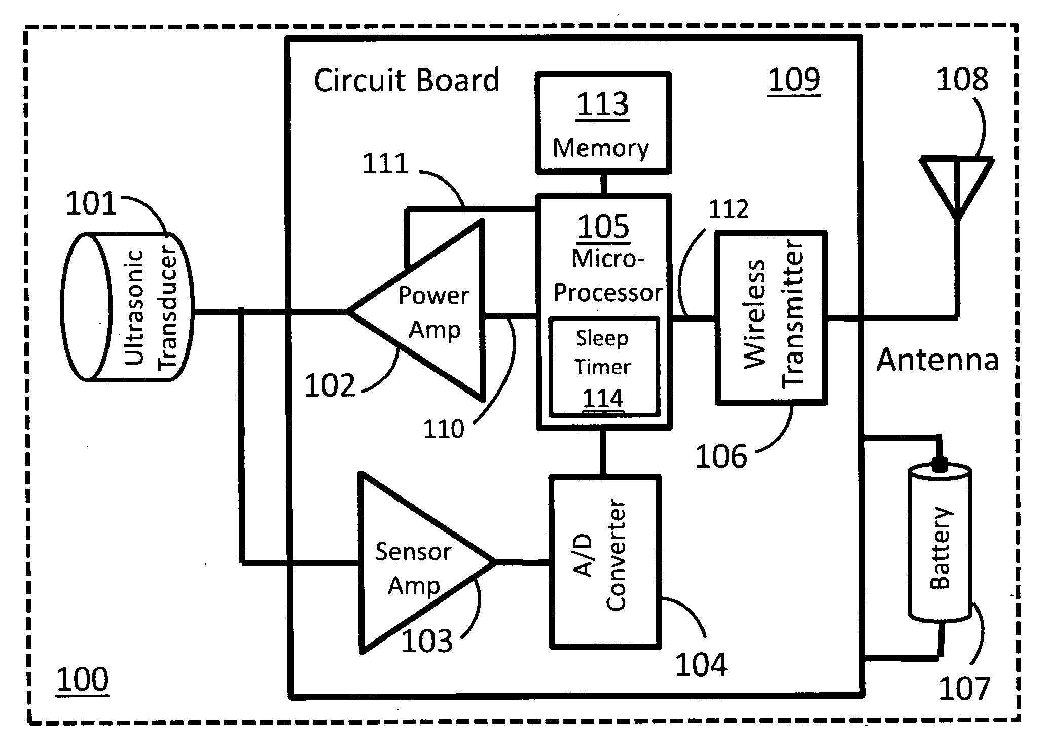
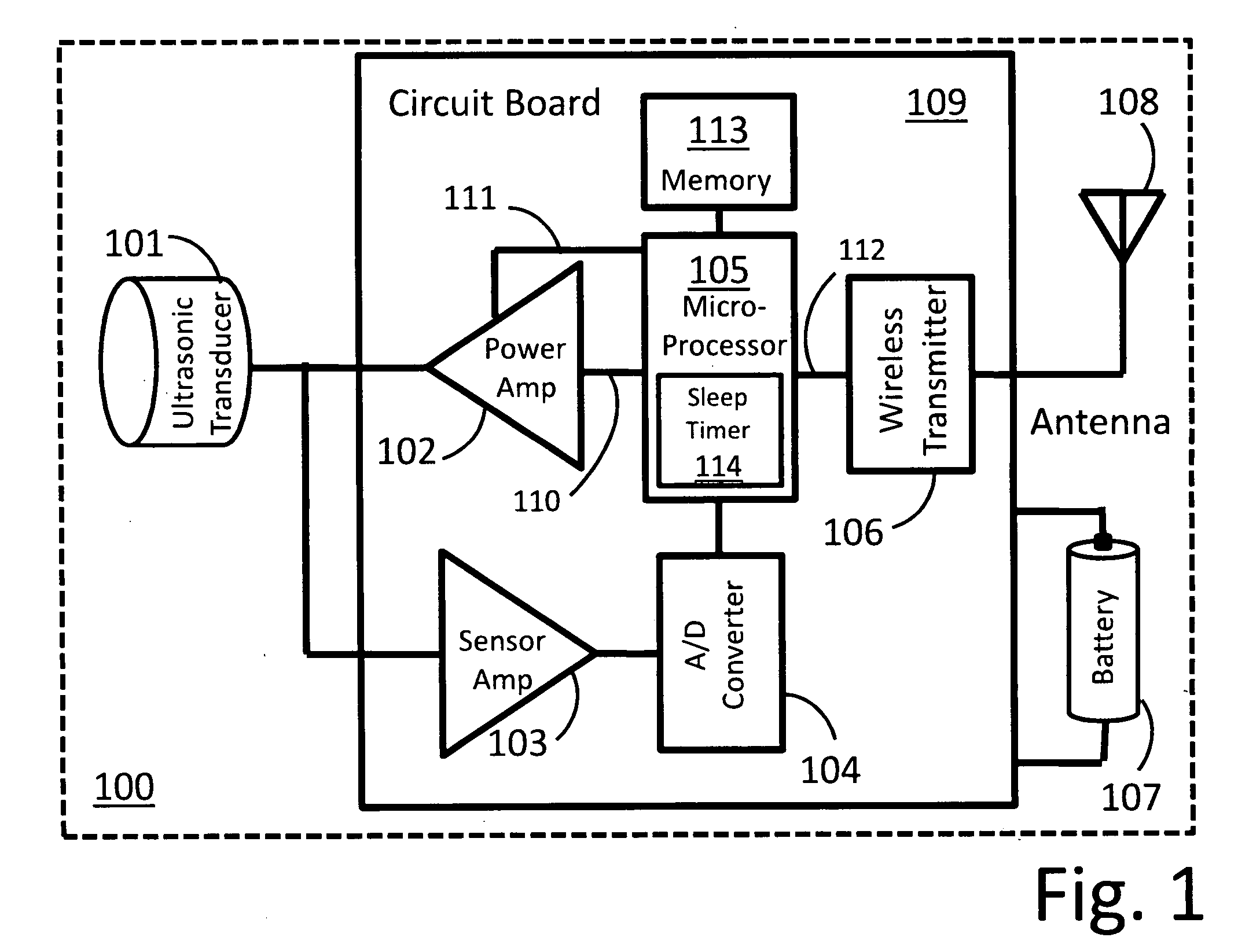
[0028]An embodiment of the present invention comprises a novel system for improving the performance of electronic devices and related methods. The following description is presented to enable a person skilled in the art to make and use the invention. Descriptions of specific embodiments are provided only as examples. Various modifications to the preferred embodiments will be readily apparent to those skilled in the art, and general principles defined herein may be applied to other embodiments and applications without departing from the spirit and scope of the invention. Thus, the present invention is not intended to be limited to the embodiments disclosed, but is to be accorded the widest scope consistent with the principles and features disclosed herein.

[0029]An embodiment of the invention herein described is a parking sensor that is simpler to install because the installer does not have to drill holes or route wires from the exterior to the interior of the car and make connections...


PUM


Abstract

A sensor for a vehicle that conserves power by alternately switching between a power on and a reduced power state. The circuit compares a most recent sensor measurement with an earlier measurement while in the power-on state and then switches to a reduced power state. A time delay generation function determines when the circuit switches out of the reduced power state depending on the result of the comparison. The duration of the reduced power state can be increased depending on the similarity of the most recent measurement to an earlier measurement.

Description

CROSS-REFERENCE TO RELATED APPLICATIONS[0001]Not applicableSTATEMENT REGARDING FEDERALLY SPONSORED RESEARCH OR DEVELOPMENT[0002]Not applicableREFERENCE TO SEQUENCE LISTING, A TABLE, OR A COMPUTER PROGRAM LISTING COMPACT DISK APPENDIX[0003]Not applicableBACKGROUND OF THE INVENTION[0004]Ultrasonic transducers are useful for detecting proximity. Proximity, or the distance from an ultrasonic transducer to an object, is detected by measuring the time it takes for a sound wave produced by the transducer to travel to the object, reflect off the object, and travel back to the transducer. Ultrasonic transducers are used in a variety of applications. One example application is in medical ultrasound imaging systems where ultrasonic sound waves are used to detect surfaces and objects inside the body such as a developing fetus. Ultrasonic transducers act as reciprocal devices, meaning that they can both transmit ultrasonic sound waves and receive or sense ultrasonic sound waves. Ultrasonic trans...

Claims


Application Information

Patent Timeline
IPC IPC(8): B06B1/00
CPCG01S7/52004G01S7/524G01S2015/938G01S15/101G01S15/931G01S15/025G01S15/86
Inventor HANKS, DARWIN MITCHELMORAIN, ROBERT ALLAN
Owner HANKS DARWIN MITCHEL
Learn More