
Divided adjustable armature for a circuit breaker

a circuit breaker and adjustable technology, applied in the direction of circuit-breaking switches, switches with electromagnetic release, protective switch details, etc., can solve the problems of non-linear system response and difficult calibration

Active Publication Date: 2010-07-29
SCHNEIDER ELECTRIC USA INC
View PDF21 Cites 3 Cited by
  • Summary
  • Abstract
  • Description
  • Claims
  • Application Information

AI Technical Summary

Benefits of technology

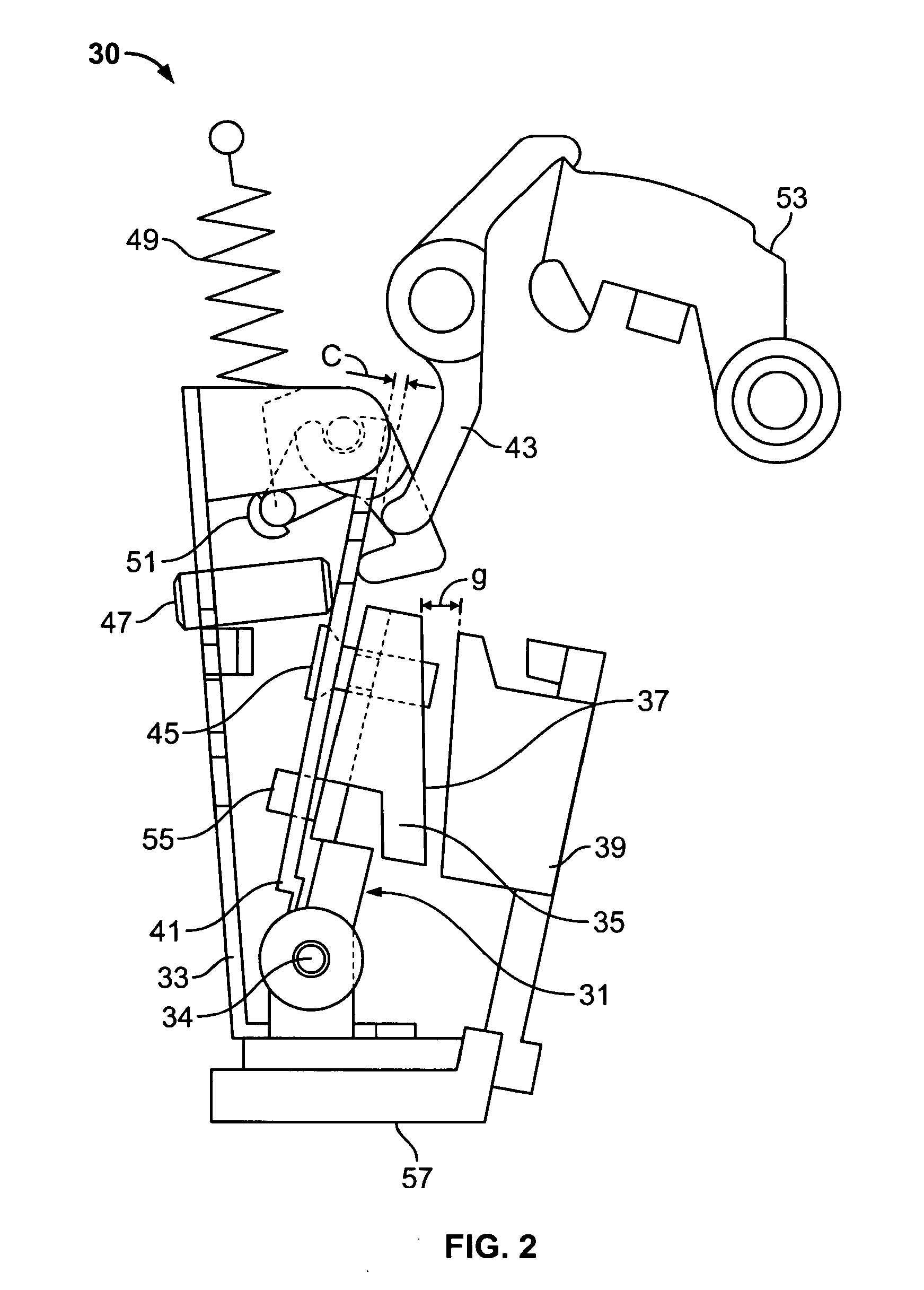
The present invention provides a divided adjustable armature for the trip mechanism of a circuit breaker that allows for two independent adjustments: the magnetic air gap between the yoke and the armature, and the clearance between the armature and the trip bar. This allows for a wider range of armature torque and higher sensitivity to magnetic air gap adjustment, while maintaining the mechanical spring force unchanged. The invention also eliminates interdependence between the clearance and the magnetic air gap, making calibration easier. The front plate and back plate of the divided armature are kept rigidly attached together, and each adjustment screw is independently controlled, resulting in higher sensitivity and a wider range of tripping current adjustment. Overall, the invention improves the performance of electromagnetic actuators and makes the circuit breaker more efficient.

Problems solved by technology

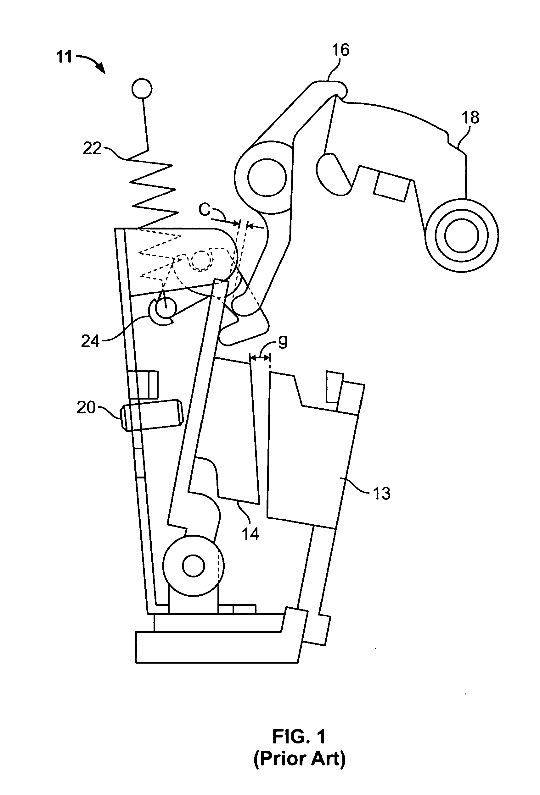
Also in the known system, the clearance (c) between the armature 14 and the trip bar 16 changes, making the system response non-linear and calibration difficult.

Method used


Image

  • Divided adjustable armature for a circuit breaker
  • Divided adjustable armature for a circuit breaker
  • Divided adjustable armature for a circuit breaker

Examples


Embodiment Construction

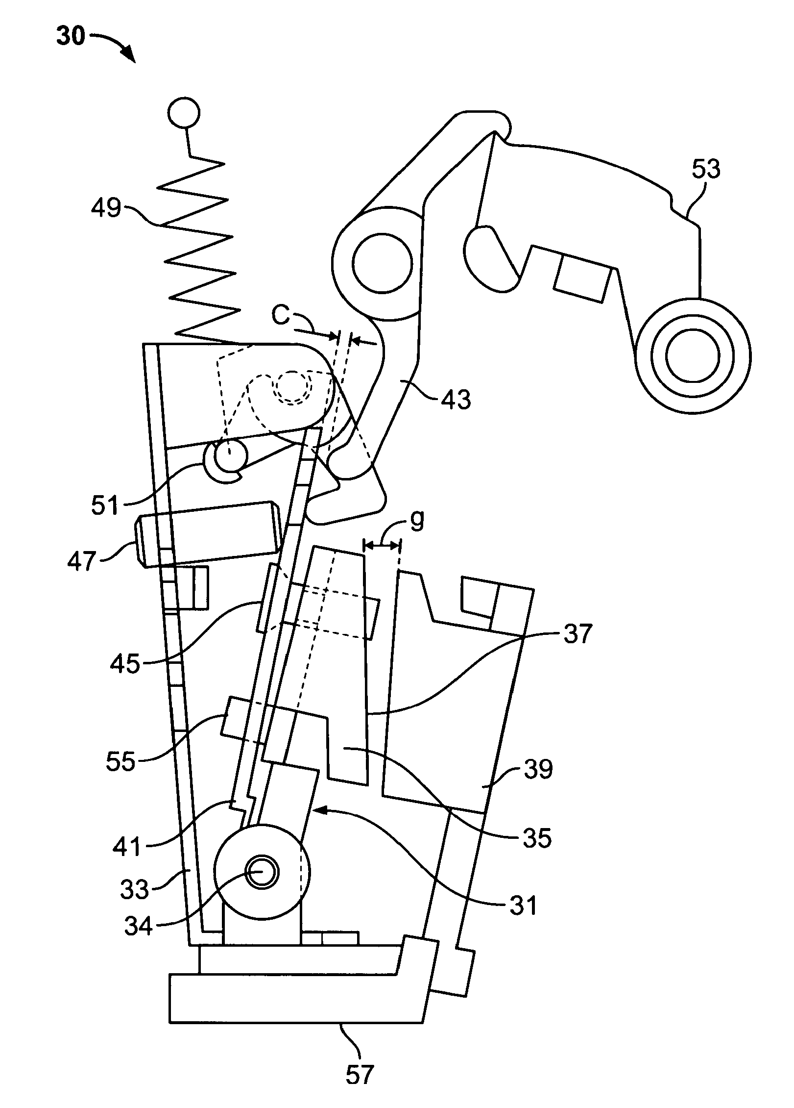
[0028]As seen in FIG. 2, a trip assembly 30 according to the present invention for a circuit breaker having a trip assembly, includes a divided armature 31 on a mounting plate 33 included within the trip assembly 30. Two sections of the divided armature 31 are a ferromagnetic front plate 35 having a surface 37 facing towards the yoke 39 and a back plate 41 attached, or settable in a fixed position relative to, the front plate 35 opposite the surface 37 facing toward the yoke 39. The back plate 41 can impinge on a trip bar 43 to initiate the opening of a circuit. A first adjustment linkage, represented by the first screw 45 between the front plate 35 and the back plate 41, rotates for adjustably setting the distance between the two plates and thereby setting a magnetic air gap “g” between the yoke 39 and the front plate 35. A second adjustment linkage, represented by screw 47 between the back plate 41 and the mounting plate 33, rotates for adjustably setting a clearance “c” between t...


PUM


Abstract

A divided armature for the trip mechanism of a circuit breaker especially useful for low trip current breakers allows for two independent adjustments: first of the magnetic air gap between the yoke and the armature and second of the clearance between the trip bar and the back plate of the armature. The divided armature allows the force of a return spring of the trip mechanism to be unchanged while adjusting the magnetic air gap to set the trip current point.

Description

RELATED APPLICATIONS[0001]This application is a Continuation of, and claims priority to, U.S. application Ser. No. 11 / 982,832, filed Nov. 5, 2007.BACKGROUND OF THE INVENTION[0002]1. Field of the Invention[0003]The present invention relates generally to electromagnetic actuators and more specifically to actuators such as trip mechanisms found in circuit breakers, accessories of circuit breakers, relays, or actuators.[0004]2. Discussion of the Related Art[0005]Referring to FIG. 1, in a known armature-yoke system 11, the input current in a conductor (not shown) within the yoke 13 creates a magnetic field in the yoke 13, the armature 14 and the magnetic air gap (g) between them. This results in a magnetic torque that rotates the armature 14 towards the stationary yoke 13 and moves the trip bar 16. The hammer 18 is then released and strikes a target device, e.g. a breaker latch release (not shown), as is understood by those in the art.[0006]The magnetic torque on the armature 14 is adjus...

Claims


Application Information

Patent Timeline
Patent Type & Authority Applications(United States)
IPC IPC(8): H01H75/10
CPCH01H71/7463H01H71/2472
Inventor FAIK, SALAHEDDINEFLEEGE, DENNIS W.
Owner SCHNEIDER ELECTRIC USA INC
Learn More