Belt-Creped, Variable Local Basis Weight Absorbent Sheet Prepared With Perforated Polymeric Belt

Active Publication Date: 2010-07-29
GPCP IP HLDG LLC
View PDF105 Cites 182 Cited by
  • Summary
  • Abstract
  • Description
  • Claims
  • Application Information

AI Technical Summary

Benefits of technology

[0012]There is provided in accordance with this invention an improved variable basis weight product which exhibits, among other preferred properties, surprising caliper or bulk. A typical product has a repeating structure of arched raised portions which define hollow areas on their opposite side. The raised arched portions or domes have relatively high local basis weight interconnected with a network of densified fiber. Transition areas bridging the connecting regions and the domes include upwardly and optionally inwardly inflected consolidated fiber. Generally speaking, the furnish is selected and the steps of belt creping, applying vacuum and drying are controlled such that a dried web is formed having: a plurality of fiber-enriched hollow domed regions protruding from the upper surface of the sheet, said hollow domed regions having a sidewall of relatively high local basis weight formed along at least a leading edge thereof; and connecting regions forming a network interconnecting the fiber-enriched hollow domed regions of the sheet; wherein consolidated groupings of fibers extend upwardly from the connecting regions into the sidewalls of said fiber-enriched hollow domed regions along at least the leading edge thereof. Preferably such consolidated groupings of fibers are present at least at the leading and trailing edges of the domed areas. In many cases, the consolidated groupings of fibers form saddle shaped regions extending at least partially around the domed areas. These regions appear to be especially effective in imparting bulk accompanied by high roll firmness to the absorbent sheet.
[0013]In other preferred aspects of the invention, the network regions form a densified (but not so highly densified as to be consolidated) reticulum imparting enhanced strength to the web.
[0017]The process can be more efficient than TAD processes using conventional fabrics, especially with respect to the use of energy and vacuum, which is employed in production to enhance caliper and other properties. A generally planar belt can more effectively seal off a vacuum box with respect to the solid areas of the belt, such that the airflow due to the vacuum is efficiently directed through the perforations in the belt and through the web. So also, the solid portions of the belt, or “lands” between perforations, are much smoother than a woven fabric, providing a better “hand” or smoothness on one side of the sheet and texture in the form of domes when suction is applied on the other side of the sheet which increases caliper, bulk, and absorbency. Without suction or vacuum applied, “slubbed” regions include arched or domed structures adjacent pileated regions which are fiber-enriched as compared with other areas of the sheet.
[0023]FIG. 1D is a plan view photomicrograph (40×) of the Yankee side of the sheet of FIGS. 1B, 1C and FIG. 1E is a 45° inclined view of the Yankee side. It is seen in these photomicrographs that the hollow regions 12 have fiber orientation bias in the CD at their leading and trailing edges as well as high basis weight at these areas. Note also, the region 12, particularly at the location indicated at 21, has been so highly densified so as to be consolidated and is deflected upwardly into the dome leading to greatly enhanced bulk. Note also, fiber orientation in the cross direction at 23.

Problems solved by technology

At consistencies above about 60 percent, it is believed there is insufficient water present to provide for sufficient reformation of hydrogen bonds between fibers as the web dries to impart the desired structural integrity to the microstructure of the web, while below about 30 percent, the web has too little cohesion to retain the features of the high solids fabric-creped structure provided by way of the belt-creping operation.

Method used


Image

  • Belt-Creped, Variable Local Basis Weight Absorbent Sheet Prepared With Perforated Polymeric Belt
  • Belt-Creped, Variable Local Basis Weight Absorbent Sheet Prepared With Perforated Polymeric Belt
  • Belt-Creped, Variable Local Basis Weight Absorbent Sheet Prepared With Perforated Polymeric Belt

Examples


examples 1-12

[0234]In Examples 1-4, belt 50, as shown in FIGS. 4-7, was used and a 50% Eucalyptus, 50% Northern Softwood blended tissue furnish was employed. FIGS. 39-40C are X-Ray tomography sections of a dome of sheet prepared in accordance with Example 3 in which FIG. 39 is a plan view of a section of the dome while FIGS. 40A, 40B and 40C illustrate sections taken along the lines indicated in FIG. 39. In each of FIGS. 40A, 40B and 40C, it can be observed that upwardly and inwardly projecting regions of the leading edge of the dome are highly consolidated.

[0235]In Examples 5-8, a belt similar to belt 100 but with fewer perforations was used and a 20% Eucalyptus, 80% Northern Softwood blended towel furnish was employed.

[0236]In Examples 9-10, a belt similar to belt 100 but with fewer perforations was used and a 80% Eucalyptus, 20% Northern Softwood layered tissue furnish was employed.

[0237]In Examples 11-12, belt 100 was used and a 60% Eucalyptus, 40% Northern Softwood layered tissue furnish wa...

examples 13-19

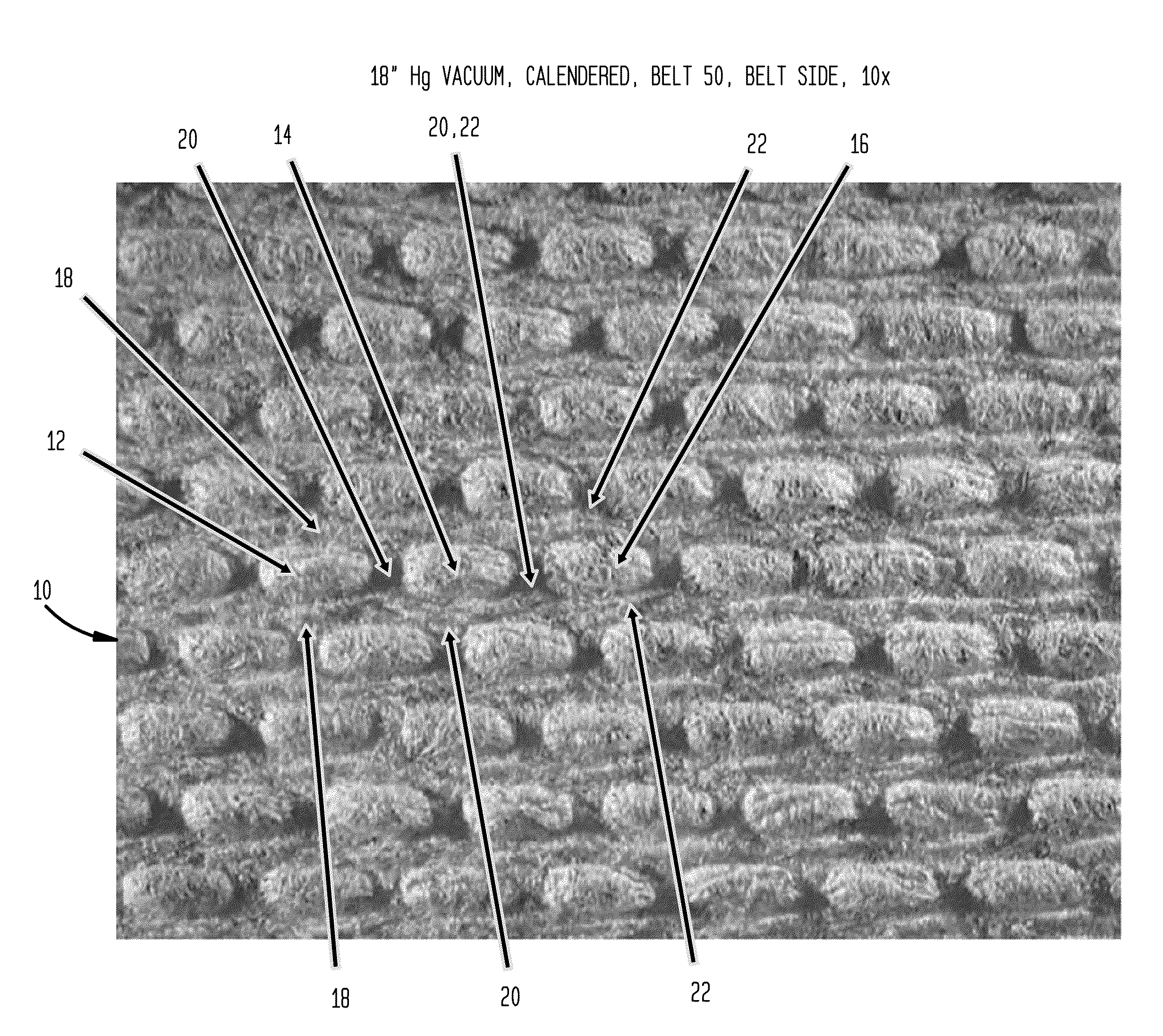
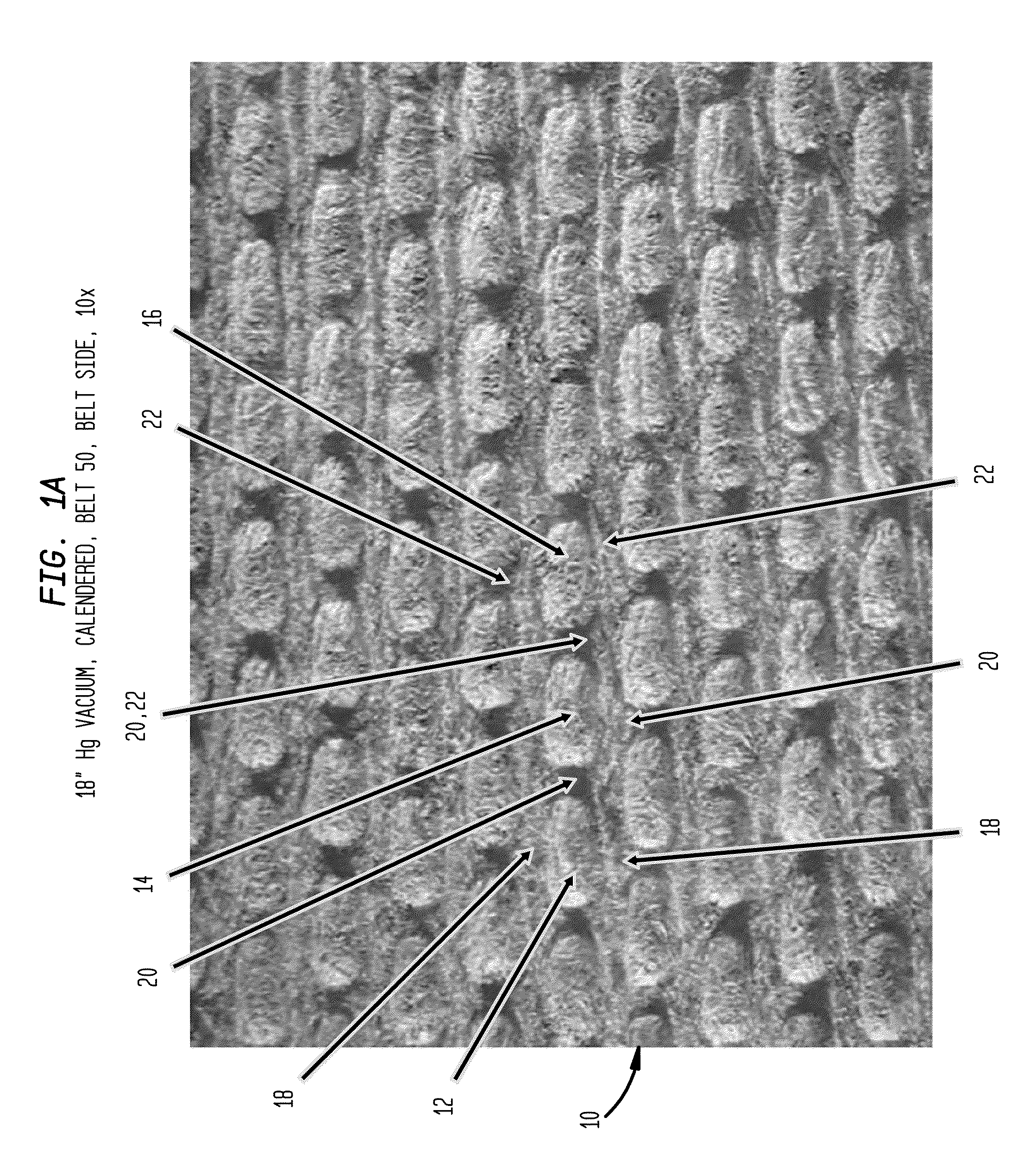
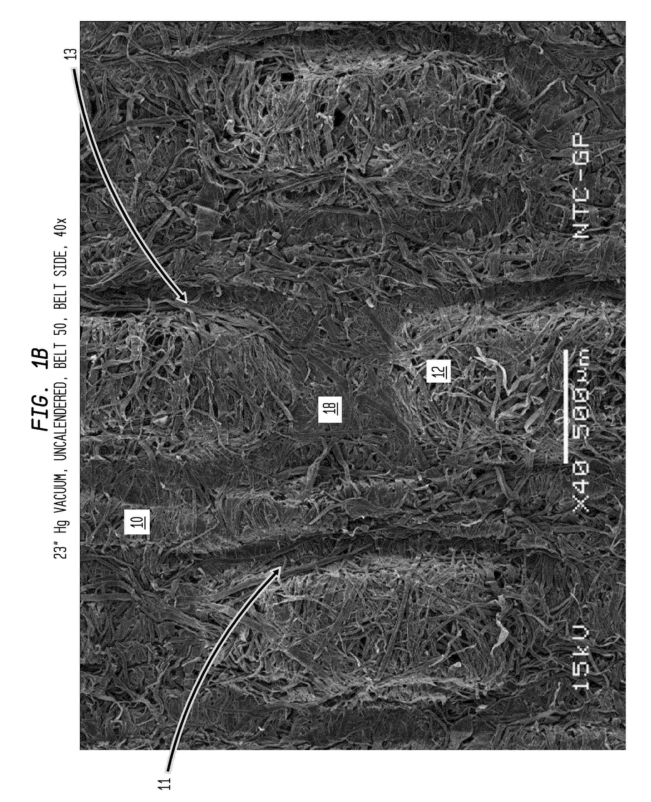
[0310]In order to quantify the results demonstrated by the photomicrographs and profiles presented supra, a set of more detailed examinations were conducted on several of the previously examined sheets as set forth along with a prior art fabric creped sheet and a competitive TAD towel as described in Table 8.

TABLE 8Basis WeightCaliper (Ave.)Example #Identification(Ave.) g / m2μFIGS.13W01328.1107.625 A-D1419682-GP28.059.3—151968028.871.226 A-F161968328.149.1—181967629.4—27 A-G19Bounty 2 ply28 A-G

[0311]More specifically, to quantitatively demonstrate the microstructure of sheets prepared according to the present invention in comparison to the prior art fabric creped sheets as well as to the commercially available TAD toweling, formation and thickness measurements were conducted on each on a detailed scale so that density could be calculated for each location in the sheet on a scale commensurate with the scale of the structure being imposed on the sheets by the belt-creping process. Thes...

examples 20-25

[0320]Samples of toweling intended for a center-pull application were prepared from furnishes as described in Table 10 which also includes data for TAD towel currently used for that application as well as the properties thereof along with comparable data for a control towel currently sold for that application produced by fabric creping technology and an EPA “compliant” towel for the same applications having sufficient post consumer fiber content to meet or exceed EPA Comprehensive Procurement Guidelines. The TAD towel is a product produced by a TAD technology which is also sold for that application. Of these, the toweling identified as 22624 is considered to be exceptionally suitable for the center-pull application as it exhibits exceptional hand panel softness (as measured by a trained sensory panel) combined with very rapid WAR, and high CD wet tensile. FIGS. 29 A-F are scanning electromicrographs of the surfaces of the 22624 toweling, while FIGS. 29 G and H illustrate the shape a...


PUM

PropertyMeasurementUnit
Lengthaaaaaaaaaa
Fractionaaaaaaaaaa
Fractionaaaaaaaaaa

Abstract

An absorbent cellulosic sheet is formed by belt creping a nascent web at a consistency of 30% to 60% utilizing a generally planar perforated polymeric creping belt to form a sheet with fiber-enriched higher basis weight hollow domed regions on one side of the sheet joined by a network of lower local basis weight connecting regions forming a network where upwardly and inwardly inflected consolidated fibrous regions exhibiting CD fiber orientation bias form transition areas between the connecting regions and the domed regions. When formed into roll products, the cellulosic sheets exhibit a surprising combination of bulk, roll firmness, absorbency and softness. The consolidated fibrous regions are preferably saddle shaped and exhibit a matted structure on both their outer and inner surfaces.

Description

CROSS-REFERENCE TO RELATED APPLICATIONS[0001]This application is based upon and claims priority of U.S. Provisional Application Ser. No. 61 / 206,146 filed Jan. 28, 2009 (Attorney Docket No. 20598; GP-08-15). This application also relates to the following United States patent applications and United States patents: U.S. patent application Ser. No. 11 / 804,246 (Publication No. US 2008-0029235), entitled “Fabric Creped Absorbent Sheet with Variable Local Basis Weight” filed May 16, 2007, (Attorney Docket No. 20179; GP-06-11), now U.S. Pat. No. 7,494,563, which was based upon U.S. Provisional Patent Application Ser. No. 60 / 808,863, filed May 26, 2006; U.S. patent application Ser. No. 10 / 679,862 (Publication No. US-2004-0238135), entitled “Fabric Crepe Process for Making Absorbent Sheet”, filed Oct. 6, 2003 (Attorney Docket No. 12389; GP-02-12), now U.S. Pat. No. 7,399,378; U.S. patent application Ser. No. 11 / 108,375 (Publication No. US 2005-0217814), entitled “Fabric Crepe / Draw Process fo...

Claims


Application Information

Patent Timeline
IPC IPC(8): B31F1/12
CPCB31F1/126D21F1/0027D21F11/006D21H27/002D21H27/02B31F1/16Y10T428/24479Y10T428/24455B31F1/122D21H11/00D21H27/007
Inventor SUPER, GUY H.RUTHVEN, PAUL J.MCCULLOUGH, STEPHEN J.SZE, DANIEL H.WENDT, GREG A.MILLER, JOSEPH H.
Owner GPCP IP HLDG LLC
Why Eureka
Try Eureka