
Wireless network device including a polarization and spatial diversity antenna system

a wireless network and antenna system technology, applied in the direction of antennas, polarisation/directional diversity, antenna supports/mountings, etc., can solve the problems of internal antennas, worse performance, and detriment to customer perception, and achieve the effect of improving radiation efficiency, radiation diagram, gain and radiation efficiency

Active Publication Date: 2010-07-22
ADVANCED DIGITAL BROADCAST
View PDF9 Cites 34 Cited by
  • Summary
  • Abstract
  • Description
  • Claims
  • Application Information

AI Technical Summary

Benefits of technology

[0016]In indoor applications, the wireless access gateway generally includes a housing which accommodates wireless access point circuitry and electrical connectors for direct plug-in into an Ethernet or telephone jacks for establishing a network communication, e.g., to the PSTN (Public Switched Telephone Network) line. Usually, the gateway has two external separate antennas pointing outward that can be manually adjusted by the user. This allows the communication quality of the antennas to be tuned according to the various ambient conditions.
[0022]The Applicant has considered that using linearly polarized antennas in the antenna system of the AG is particularly advantageous since they generally guarantee a relatively high uncorrelation between the antennas when polarization diversity is implemented.
[0023]The Applicant has found that an AG comprising an antenna system having at least two linearly polarized antennas with orthogonal polarization and having a radiating element lying on perpendicular planes is able to maintain communication quality when the AG is placed in different operating positions. At least one of the two antennas is arranged on a plane that is parallel to the bottom wall of the housing of the AG, the bottom wall being the base of the AG when horizontally arranged on a supporting surface. The access gateway includes a main circuit board overlying the bottom wall and having an upper surface being substantially parallel to the bottom wall.
[0024]The Applicant has found that the main circuit board acts as reflecting surface that reflects the radiation field emitted by the antennas and that it is in particular advisable to dispose the antenna arranged on a plane that is parallel to the bottom wall in the proximity of the plane defined by the upper surface of the main circuit board in order to improve radiation gain of the antenna system since distortions due to reflections from the main circuit board are greatly reduced.
[0025]Advantageously, each of the antennas of the antenna system is a planar antenna since it allows the configuration of the antenna assembly with a certain degree of freedom and facilitates the integration of the antennas in the housing.
[0026]Preferably, each of the antennas of the antenna system can produce a radiation pattern that is substantially omni-directional with respect to a predetermined plane.

Problems solved by technology

Nevertheless, external antennas increase the encumbrance of the gateway and often do not harmonize with the gateway casing leading to a detrimental impact on the customer perception.
On the other hand, internal antennas, i.e., antennas that are mounted inside the housing of the electronic device functioning as an access point, even if they improve the packaging style of the electronic equipment casing, have worse performance, in terms of radiation diagram, gain, and radiation efficiency, with respect to external antennas, since they are affected by the presence of other electronic components of the device.
In addition, internally mounted antennas have a size constraint due to the dimensions and shape of the electronic equipment package.

Method used


Image

  • Wireless network device including a polarization and spatial diversity antenna system
  • Wireless network device including a polarization and spatial diversity antenna system
  • Wireless network device including a polarization and spatial diversity antenna system

Examples


Embodiment Construction

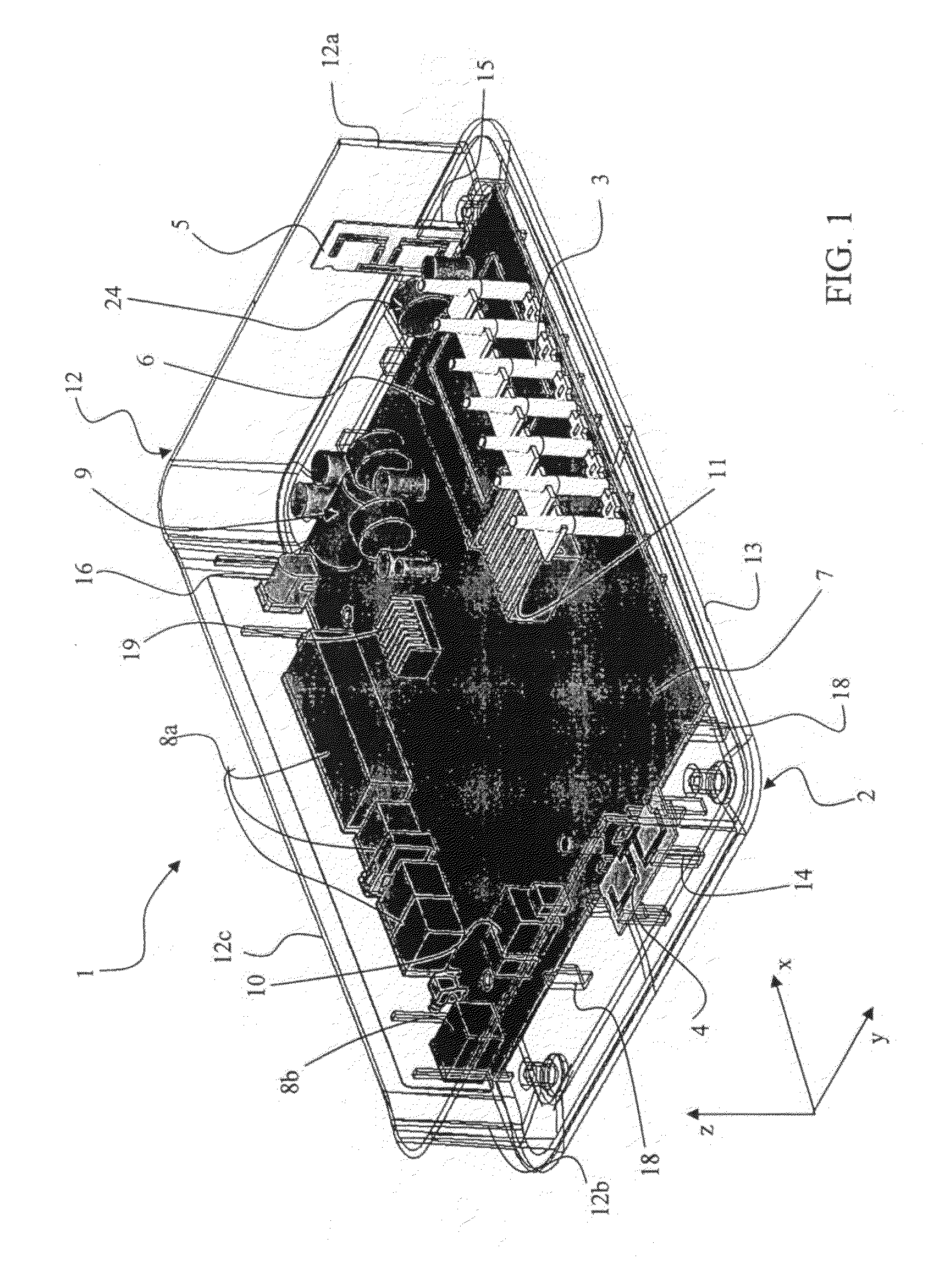
[0043]FIGS. 1 and 2 illustrate a section of a schematic perspective view and a top planar view, respectively, of an access gateway (AG) according to a preferred embodiment of the present invention. Access gateway 1 is a wireless network device that may act as an entrance point to another network, for example the Internet or a mobile communication network. In a simplest WLAN configuration for small service areas and limited radio coverage, for example home multimedia application, the access gateway itself can provide the radio interface. In the preferred embodiments, the access gateway comprises a radio front-end, i.e., a system unit that processes radio-frequency (RF) signals in the send and receive directions, with an antenna system (detailed below) controlled by a proper RF switching technique.

[0044]The AG 1 is enclosed in an open-top housing 2 comprising a bottom wall 13 and peripheral enclosure 12 made of side walls 12a and 12b, opposite one another, rear wall 12c and front wall...


PUM


Abstract

A wireless access gateway for communication of wave signals at radio frequencies within a frequency band, includes an access gateway enclosed in a housing including a bottom wall and a main circuit board overlying the bottom wall and having an upper surface substantially parallel to the bottom wall. The gateway is equipped with an antenna system including at least two antennas: a first linearly polarized antenna for propagating a first wave signal along a first polarization axis including a first radiating element extending along a first longitudinal axis lying on a first plane substantially parallel to the base plane, and a second linearly polarized antenna for propagating a second wave signal along a second polarization axis oriented perpendicularly to the first polarization axis, the second antenna including a second radiating element extending along a second longitudinal axis lying on a second plane oriented perpendicularly to the first plane. The first and second antennas are positioned relative to each other at a distance of at least λ / 2, where λ is the wavelength corresponding to a radio frequency within the frequency band.

Description

FIELD OF THE INVENTION[0001]The present invention relates to a wireless network device and in particular to a device functioning as access point between one or more mobile terminals and a wired network.BACKGROUND OF THE INVENTION[0002]Broadband access technologies have allowed service providers to expand their content and service offerings to both business and home users. For example, a user may subscribe to multiple services or applications, such as voice service, Internet access service, video streaming, a gaming service, etc. from one or more service providers. These services and / or applications available through a private or public data network (e.g., the Internet) may be delivered over a single network connection, such as a Digital Subscriber Line (DSL) line.[0003]Wireless local area networks (WLANs), like their wired counterparts, are being developed to provide high bandwidth to users in a limited geographical area. They are being developed as an alternative to the high instal...

Claims


Application Information

Patent Timeline
IPC IPC(8): H01Q1/24H01Q21/28
CPCH01Q1/2291H01Q21/24H01Q21/28H04B7/10
Inventor BARBIERI, DANIELEBOFFA, VICENZOGERMANI, SIMONERICCI, FABRIZIOSTORTO, MARCO
Owner ADVANCED DIGITAL BROADCAST
Learn More