
Driver Device for a Load and Method of Driving a Load With Such A Driver Device

a technology of driver device and load, which is applied in the direction of electric variable regulation, process and machine control, instruments, etc., can solve the problems of creating additional losses or having unwanted influence on led behavior, and achieve the effect of avoiding additional losses or influences on load behavior

Active Publication Date: 2010-07-22
SIGNIFY HLDG BV
View PDF11 Cites 40 Cited by
  • Summary
  • Abstract
  • Description
  • Claims
  • Application Information

AI Technical Summary

Benefits of technology

The present invention provides a driver device for a load, particularly a light unit, which overcomes the limitations of previous driver devices. The driver device has its own power supply, which is not necessary to feed the control circuit additional wires. The energy storage element is connected in parallel to the load and the control unit activates the shunting switch to recharge the energy storage element when the load is turned off. The recharge control circuitry includes a control switch or a DC / DC converter that is activated when the energy storage element reaches a predetermined reference value. The driver device is advantageous for controlling LED or OLED light units and can be used in a variety of applications. The invention also provides a method for driving a load with the driver device.

Problems solved by technology

In most cases, the second solution will create additional losses or will have unwanted influence on the LED behavior.

Method used


Image

  • Driver Device for a Load and Method of Driving a Load With Such A Driver Device
  • Driver Device for a Load and Method of Driving a Load With Such A Driver Device

Examples


Embodiment Construction

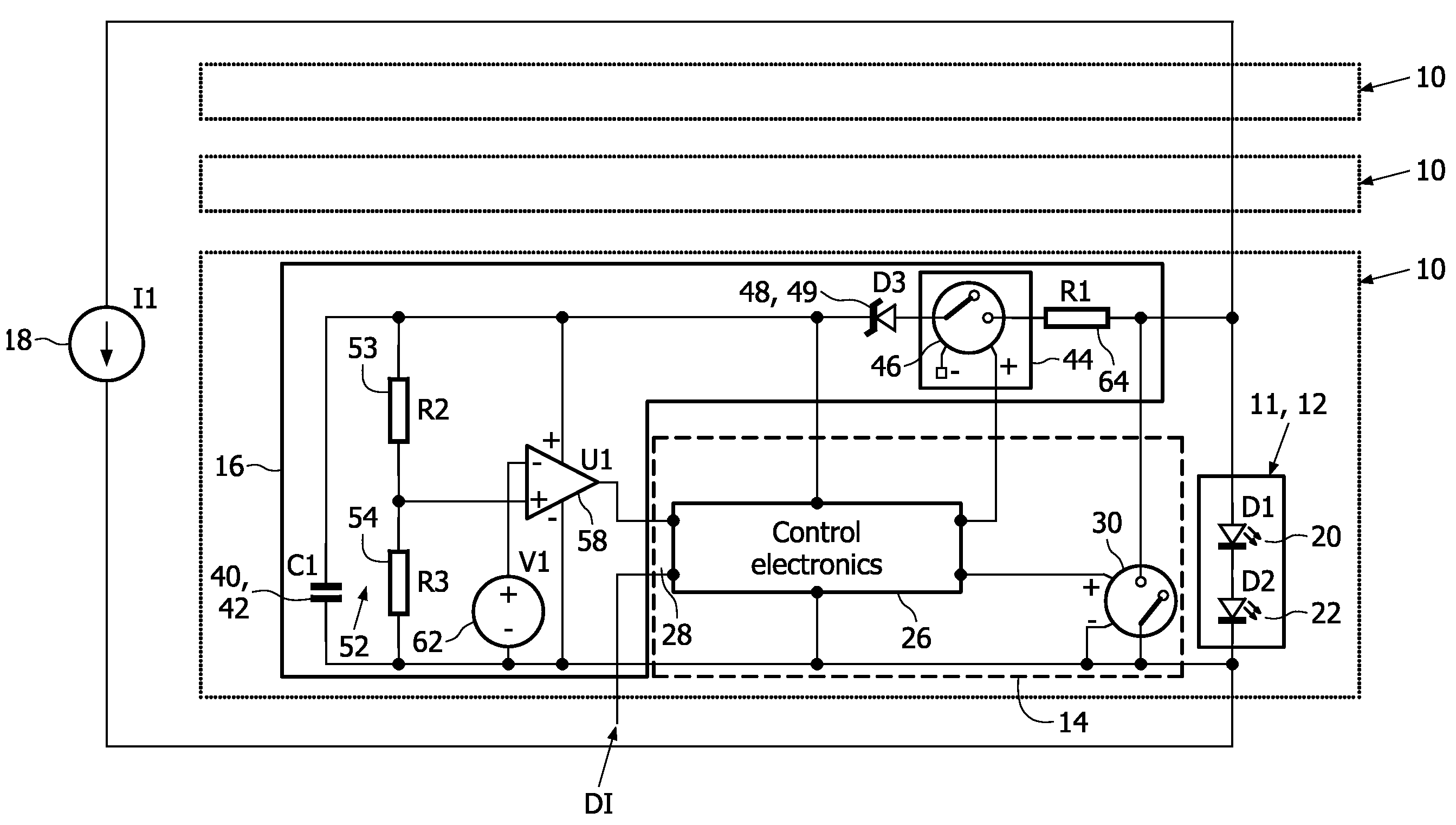
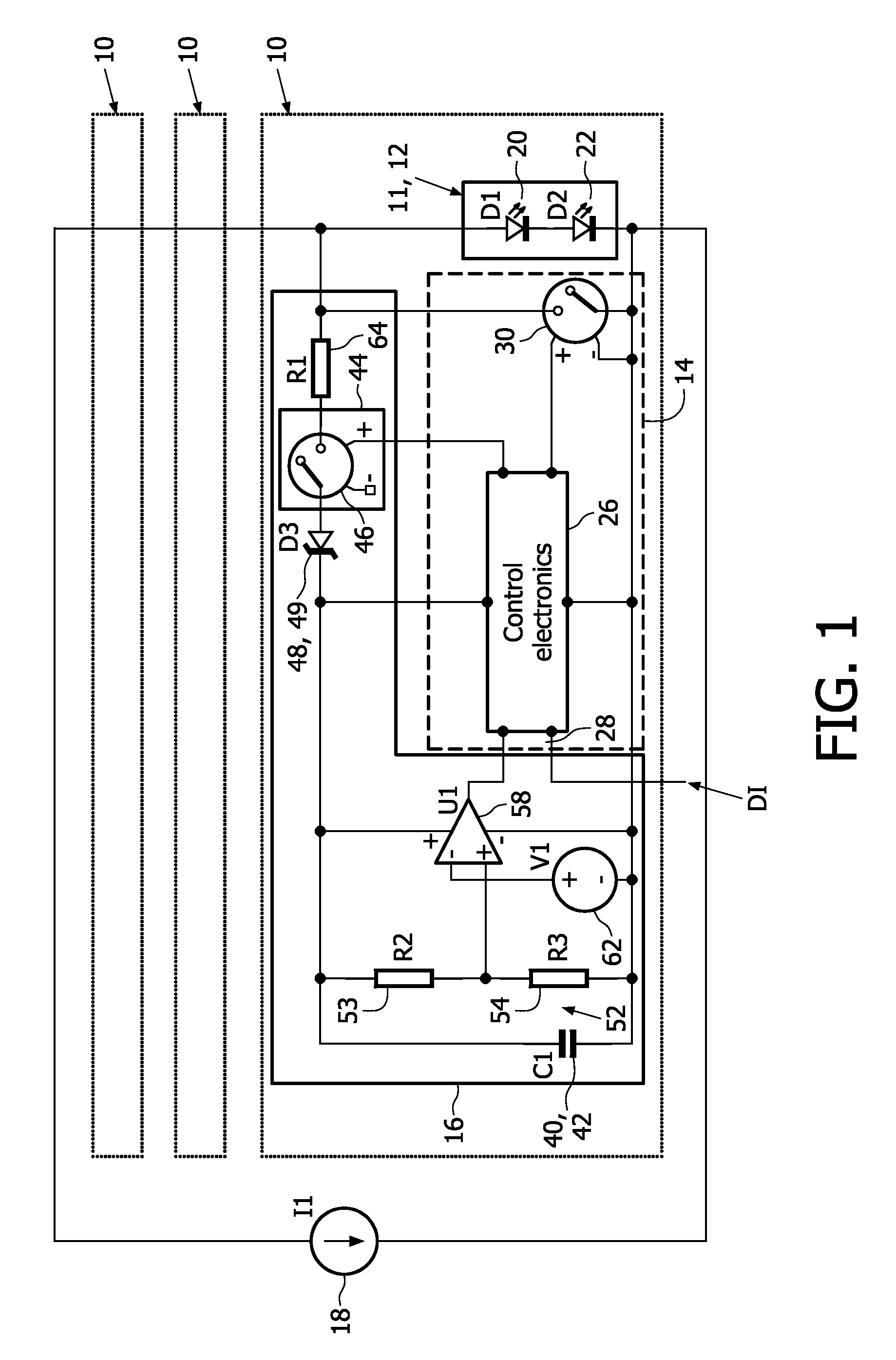
[0045]The driver device 10 comprises a load 11, which is preferably provided as a light unit 12 in the present embodiment. The light unit 12 is preferably an LED unit, comprising one or more LEDs 20, 22. As already mentioned before, “LED” means LED or OLED or a series connection or a parallel connection or a mixed series and parallel connection of LED and / or OLED elements.

[0046]The serially-connected LEDs 20, 22 are driven by a current source 18 supplying a current I1. The current source 18 is not part of the driver device 10.

[0047]The driver device 10 further comprises a control unit 14 and an energy storage unit 16.

[0048]The control unit 14 comprises a control circuit 26 and a shunting switch 30 which is coupled parallel to the light unit 12. The shunting switch 30, which is preferably an electronic switch like a transistor or a field effect transistor, is controlled by the control circuit 26 and serves to shunt the light unit 12.

[0049]If the shunting switch 30 is open or off, the...


PUM


Abstract

The invention relates to a driver device for a load (11), particularly an LED / OLED unit (12; 20, 22), comprising a shunting switch (30) parallel to the load, a control unit (14, 26) for controlling the shunting switch (30), an energy storage element (40) adapted to supply energy to at least the control unit (14, 26), and a recharge control circuitry (46) arranged in series with the energy storage element (40), the series connection of energy storage element (40) and recharge control circuitry (46) being provided parallel to the shunting switch (30), wherein said control unit (14, 26) is adapted to activate said recharge control circuitry (46) and to switch said shunting switch (30) off, when said energy storage element (40) is to be recharged. The invention also relates to a method of driving a load (11).

Description

FIELD OF THE INVENTION[0001]The present invention relates to a driver device for a load, particularly an LED / OLED unit. The invention also relates to a method of driving a load with such a driver device.BACKGROUND OF THE INVENTION[0002]Light emitting diodes (LEDs) or organic light emitting diodes (OLEDs) will increasingly be used for decorative purposes or for display applications. To have a high resolution and smooth transitions, a large number of light spots are required. In many of these applications, electronic circuits are used to control the LEDs, particularly the status (on / off) of the LED. As it is known in the art, the on / off condition can be controlled via a shunting switch which is coupled parallel to the respective LED. If the shunting switch is on (closed), the LED is shunted and, hence, off. If the shunting switch is off (open), the LED is on, since the drive current does not flow through the shunting switch. Beside the status (on / off) of the LED, its average brightnes...

Claims


Application Information

Patent Timeline
Patent Type & Authority Applications(United States)
IPC IPC(8): H05B41/36G05F1/613H05B44/00
CPCH02M2001/0006H05B33/0818Y02B20/347Y02B20/346H05B33/083H05B45/48Y02B20/30H05B45/3725H02M1/0006
Inventor RADERMACHER, HARALD JOSEF GUENTHERWENDT, MATTHIAS
Owner SIGNIFY HLDG BV
Learn More