Lighting apparatus

a technology of lighting apparatus and light source, which is applied in the direction of lighting and heating apparatus, incadescent envelope/vessel, light source combination, etc., can solve the problems of large area illumination burden of industrial and commercial buildings, associated amount of heat, and time periods with less than desired lighting coverage, so as to achieve less wattage consumption, less wattage consumption, and less heat dissipation

Inactive Publication Date: 2010-07-22
WALTON RANDAL
View PDF17 Cites 9 Cited by
  • Summary
  • Abstract
  • Description
  • Claims
  • Application Information

AI Technical Summary

Benefits of technology

[0023]The importance stems from the amount of space needed to allow the reflector to bounce light back past the tubes and toward the TIA, and also the space needed for dissipation of heat. Convection allows cool air to be drawn past the fins and dissipating heat will protect the ballast. The compact fluorescent floodlight has a lens designed to precisely control the light from the reflector. It is covered with small, detailed shapes to direct the light into the desired beam pattern. The lens also acts as a cover to allow the lamp to act as it own fixture.
[0024]A second embodiment of applicant's invention employs an “implant” consisting of a spirally configured fluorescent or compact fluorescent lamp which is fitted with a reflective surface proximate to the interior portion of the lamp itself. This implant may be retrofitted into a conventional high-bay industrial fixture, thereby delivering an equivalent amount of light to the TIA with less wattage consumed. Each spiral lamp has proximate to it a primary reflector to re-direct light which might otherwise be “lost,” meaning not directed to the TIA, and as well, a secondary reflector which helps direct the light to a third reflector which finally directs the focused light to the TIA.
[0025]A third embodiment of applicants invention employs a high intensity disc

Problems solved by technology

Many industrial and commercial buildings have the burden of illuminating large areas from standard height as well as from higher than normal ceilings.
Mercury vapor, sodium and other high intensity discharge lamps in commercial applications may consume as much as 400 to 1000 watts, and generate an associated amount of heat, contributing to additional heating, ventilating and air conditioning (“HVAC”) operation and fire protection consideration

Method used


Image

  • Lighting apparatus
  • Lighting apparatus
  • Lighting apparatus

Examples


Embodiment Construction

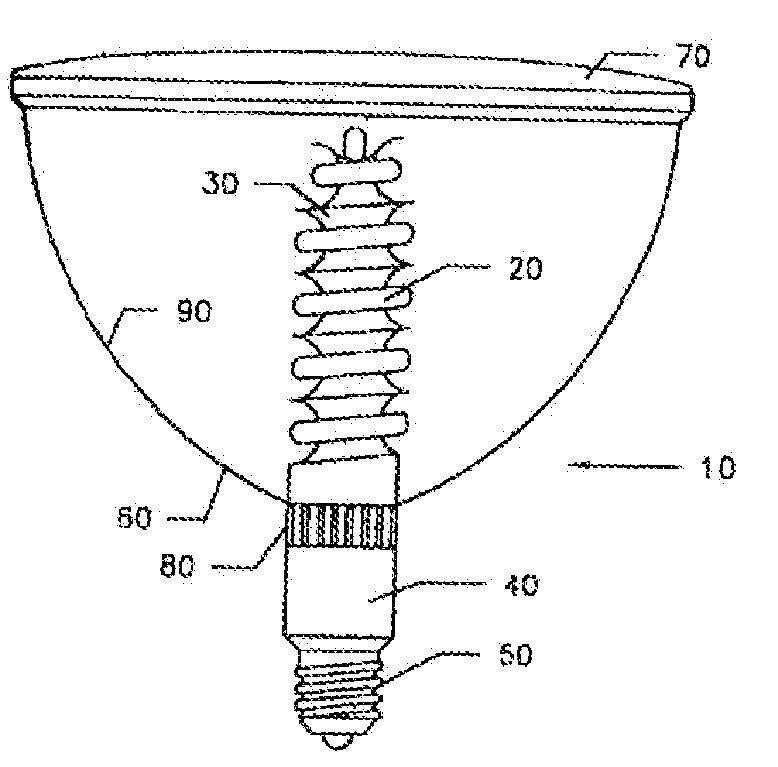
[0074]As seen in FIG. 1, a flood light 10 comprises a spiral compact fluorescent lamp 20 around which a primary reflector 30 is positioned. A first bonding means, such as glue or other adhesive or mechanical means is employed to fix lamp 20 and primary reflector 30 in a predetermined position. Lamp 20 is constructed in accordance with typical fluorescent lamps, comprising phosphor coating applied to the inside of the tube with hot cathodes at each end of the lamp. Air is exhausted through the exhaust tube during manufacture and an inert gas is introduced into the bulb. A minute quantity of liquid mercury is included with gas, the gas is usually argon. The stem press has lead-in-wires connecting the base pins and carry the current to and from the cathodes and the mercury arc. Reflector 30 may be fashioned from a variety of materials including but not limited to chrome-plated glass, chrome-plated metal, polished or painted aluminum plate, painted glass, and painted plastic with a vari...


PUM


Abstract

A lighting apparatus including a reflector having a reflective exterior surface partially enclosing an interior space and defining a focal point within the interior space, and a high pressure discharge lamp positioned substantially at the focal point of the reflective exterior surface. In some examples, the high pressure discharge lamp includes an arc tube containing mercury, a metal halide, or sodium. In some examples, the reflective exterior surface extends along a longitudinal axis and curves around the longitudinal axis. In some example, the reflective exterior surface defines an elliptical paraboloid.

Description

CROSS-REFERENCE TO RELATED APPLICATIONS[0001]This is a continuation-in-part of copending application Ser. Nos. 10 / 393,816, filed on Mar. 21, 2003; 11 / 588,959, filed on Oct. 27, 2006; and 12 / 070,712, filed on Feb. 19, 2008, which are hereby incorporated by reference for all purposes.FIELD OF THE INVENTION[0002]The instant invention may be considered to be in the field of lighting devices, specifically lamps of high intensity discharge and fluorescent lamps, but not limited thereto.BACKGROUND OF INVENTION[0003]Many industrial and commercial buildings have the burden of illuminating large areas from standard height as well as from higher than normal ceilings. One solution to this lighting application has been the use of high intensity discharge lamps. Mercury vapor, sodium and other high intensity discharge lamps in commercial applications may consume as much as 400 to 1000 watts, and generate an associated amount of heat, contributing to additional heating, ventilating and air conditi...

Claims


Application Information

Patent Timeline
IPC IPC(8): H01J5/16
CPCF21Y2103/022F21Y2111/00F21Y2113/00H01J5/54H01J61/025H01K7/02H01J61/34H01J61/35H01K1/18H01K1/325H01J61/327F21Y2103/33
Inventor WALTON, RANDAL
Owner WALTON RANDAL
Why Eureka
Try Eureka