
Kneaded dough dividing apparatus

Active Publication Date: 2010-07-22
OSHIKIRIKK
View PDF12 Cites 7 Cited by
  • Summary
  • Abstract
  • Description
  • Claims
  • Application Information

AI Technical Summary

Benefits of technology

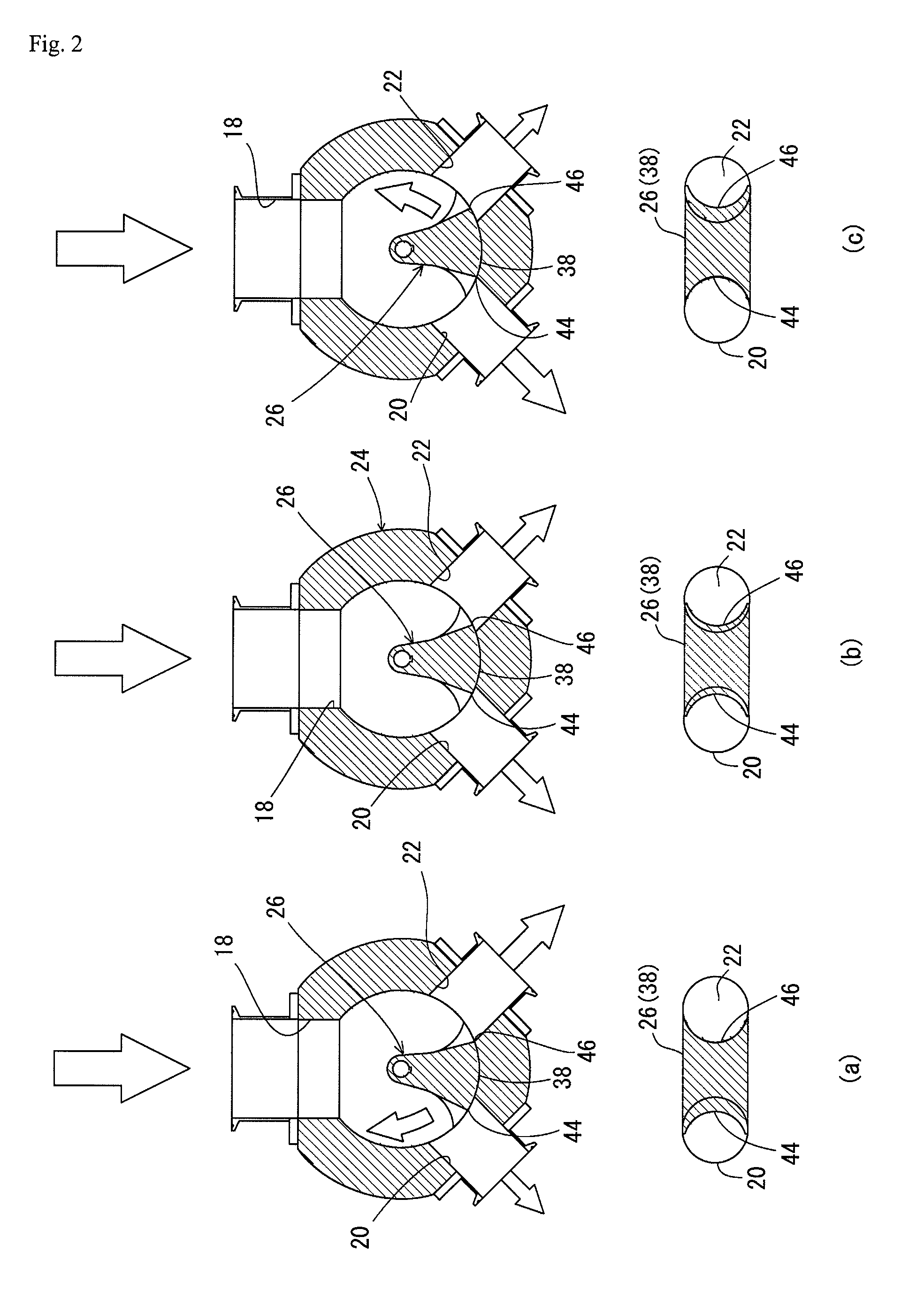
[0011]The present invention provides a kneaded dough dividing apparatus having a divider including a divider vessel body having one dough inlet that receives continuously supplied kneaded dough and two dough outlets for discharging the kneaded dough as two streams of kneaded dough. The divider further includes an outlet control member provided in the divider vessel body to simultaneously partially close the two dough outlets. The outlet control member is displaceable relative to the two dough outlets to reduce the opening area of one of the two dough outlets when enlarging the opening area of the other of the two dough outlets and to reduce the opening area of the other dough outlet when enlarging the opening area of the one dough outlet.
[0012]The kneaded dough dividing apparatus of the present invention is provided with a closing member that simultaneously partially closes two dough outlets. The closing member acts to increase the opening area of one of the two dough outlets when decreasing the opening area of the other dough outlet. Therefore, the total amount of kneaded dough discharged from the kneaded dough dividing apparatus can be kept substantially constant, and hence the pressure in the divider vessel body can be kept substantially constant. Thus, the quality of kneaded dough discharged from the apparatus can be kept constant.
[0015]More specifically, the inner peripheral wall surface may have a circular cylindrical shape. This facilitates the production of the divider vessel body.

Problems solved by technology

When divided into a plurality of streams of kneaded dough through the kneaded dough dividing apparatus, the kneaded dough needs to be divided under equal conditions for all the streams of dough; otherwise it is likely that the divided streams of dough will vary from each other in terms of dough texture, and when small pieces of cut kneaded dough are baked, it will be difficult to obtain bread products of uniform quality.
Because the kneaded dough is forced into the manifold of large volumetric capacity from one inlet under pressure, the kneaded dough is likely to circulate or partly reside in the manifold, and it is difficult to make uniform the pressure in the manifold.

Method used


Image

  • Kneaded dough dividing apparatus
  • Kneaded dough dividing apparatus
  • Kneaded dough dividing apparatus

Examples


Embodiment Construction

[0032]Embodiments of the kneaded dough dividing apparatus according to the present invention will be explained below with reference to the accompanying drawings.

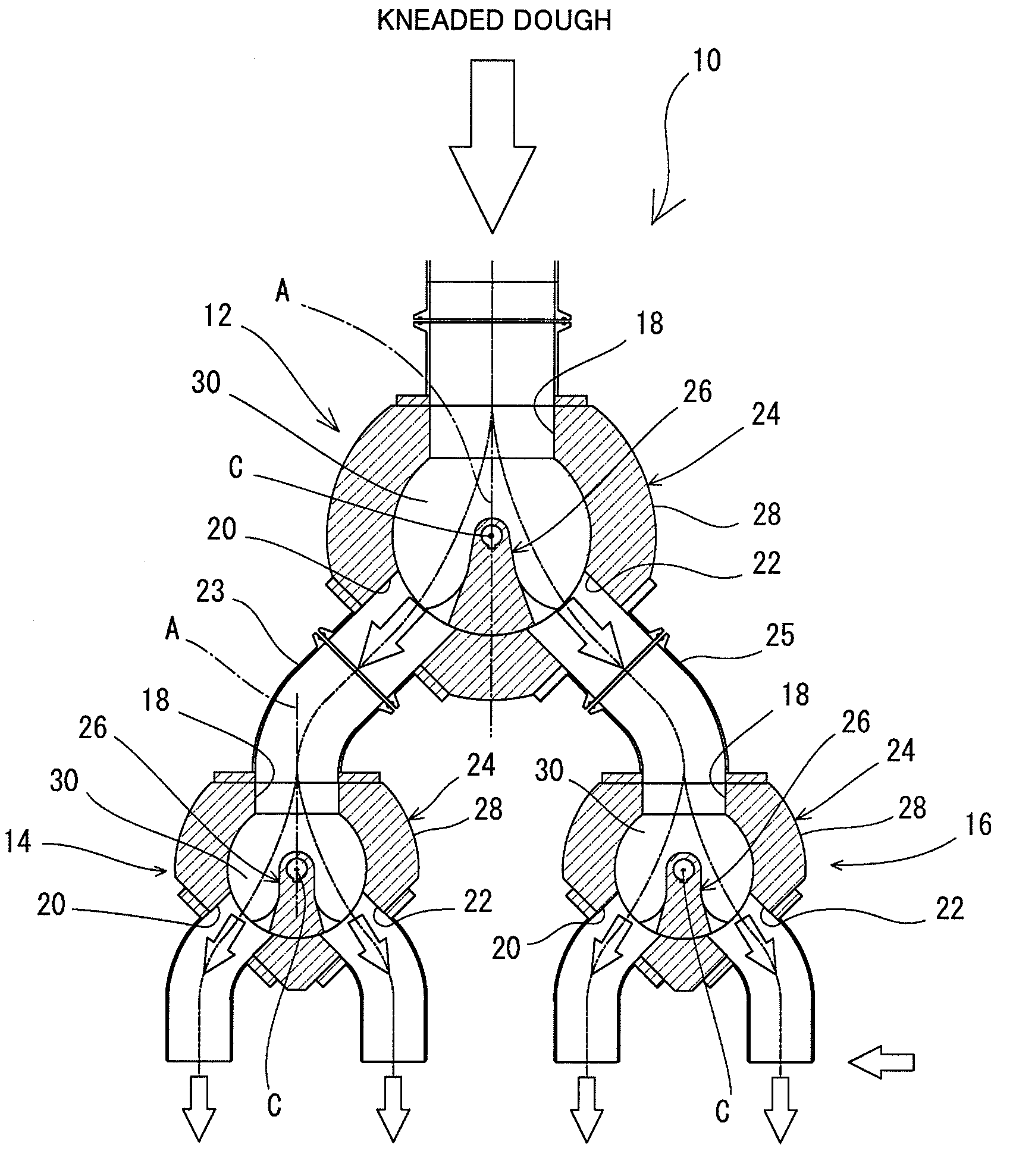
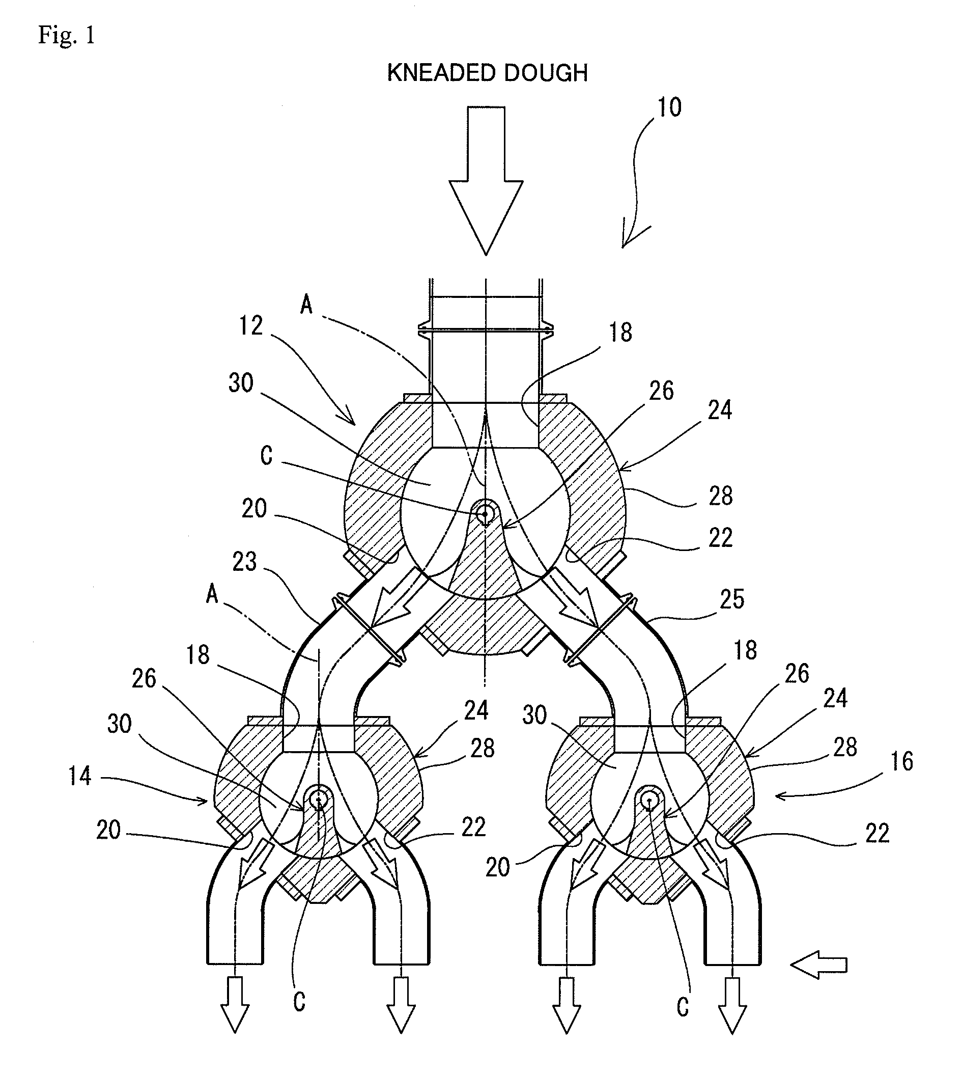
[0033]FIG. 1 is a diagram showing the basic structure of the kneaded dough dividing apparatus 10 according to the present invention. This apparatus divides kneaded dough, e.g. bread dough, supplied thereto into four streams of dough. At the downstream side of each of the four divided streams of dough, a cut-off device (not shown) is provided to cut off the associated stream of dough into small pieces (each corresponding to one bread product to be baked).

[0034]That is, the kneaded dough dividing apparatus 10 has a first divider 12 that divides kneaded dough supplied from a dough supply pump (not shown) at the upstream side into two streams of dough, and second and third dividers 14 and 16 that respectively receive the two streams of kneaded dough divided by the first divider 12 and that each divide the received kneaded dough ...


PUM


Abstract

A kneaded dough dividing apparatus has a divider vessel body (24) having a dough inlet (18) and two dough outlets (20, 22) for discharging kneaded dough as two streams of dough. The divider vessel body is provided therein with an outlet control member (26) that simultaneously partially closes the two dough outlets. The outlet control member is displaceable relative to the two dough outlets (20, 22) to reduce the opening area of one of the two dough outlets when enlarging the opening area of the other of the two dough outlets and to reduce the opening area of the other dough outlet when enlarging the opening area of the one dough outlet.

Description

TECHNICAL FIELD[0001]The present invention relates to a kneaded dough dividing apparatus that divides and delivers continuously supplied kneaded dough as a plurality of streams of kneaded dough.BACKGROUND ART[0002]In the production of bread, a mass of kneaded dough (batch) is prepared in a mixer, and this mass of kneaded dough is extruded as a continuous stream of kneaded dough by a pump and then divided into a plurality of streams of kneaded dough through a kneaded dough dividing apparatus. Thereafter, each stream of kneaded dough is divided into small pieces necessary for bread baking.[0003]When divided into a plurality of streams of kneaded dough through the kneaded dough dividing apparatus, the kneaded dough needs to be divided under equal conditions for all the streams of dough; otherwise it is likely that the divided streams of dough will vary from each other in terms of dough texture, and when small pieces of cut kneaded dough are baked, it will be difficult to obtain bread p...

Claims


Application Information

Patent Timeline
IPC IPC(8): A47J43/00
CPCA21C5/00
Inventor OKI, YUZURUUMETSU, MASAMIHASEGAWA, TAKAHIRO
Owner OSHIKIRIKK
Learn More