Maximum likelihood decoder and information reproduction apparatus
- Summary
- Abstract
- Description
- Claims
- Application Information
AI Technical Summary
Benefits of technology
Problems solved by technology
Method used
Image

Examples
first embodiment
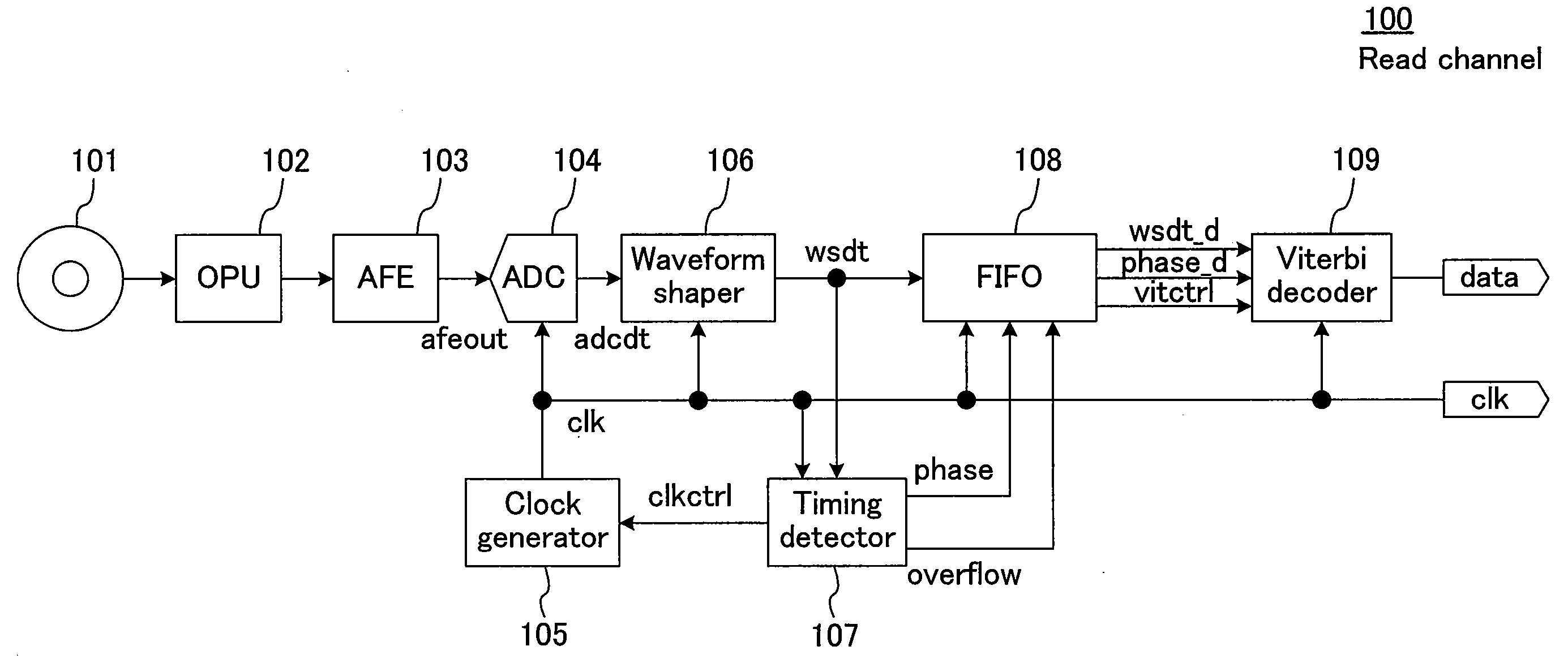
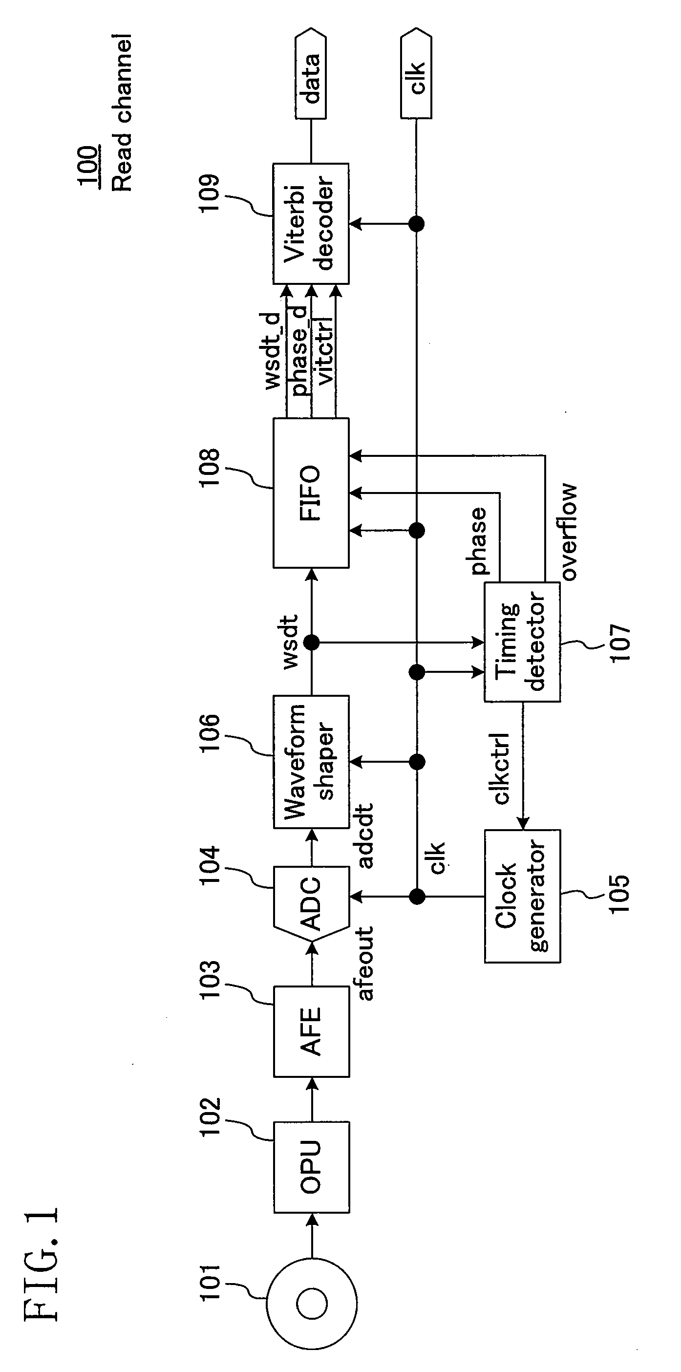
[0056]FIG. 1 schematically illustrates a read channel 100 as an information reproduction apparatus according to a first embodiment of the present invention. In FIG. 1, digital data is stored in an optical disk 101. In the read channel 100, this recorded data and a clock that is in synchronization with this recorded data are extracted. Although the optical disk 101 is used in this embodiment, the present invention is not limited to the optical disk 101, but is applicable to magnetic disks and magneto-optical disks and also to radio communication and wire communication.
[0057]Hereinafter, operation of the read channel 100 will be described in the order of signal flow. The digital data recorded on the optical disk 101 is read by an optical pickup (a read section) 102 and is then output as an analog signal containing recording-timing information. An analog frontend (an analog waveform shaping section) 103 performs analog processing, in which the amplitude and level of the analog signal f...
second embodiment
[0076]Next, a second embodiment of the present invention will be described.
[0077]FIG. 4 illustrates the internal configuration of a Viterbi decoder 109′, which is an information reproduction apparatus according to the second embodiment of the present invention.
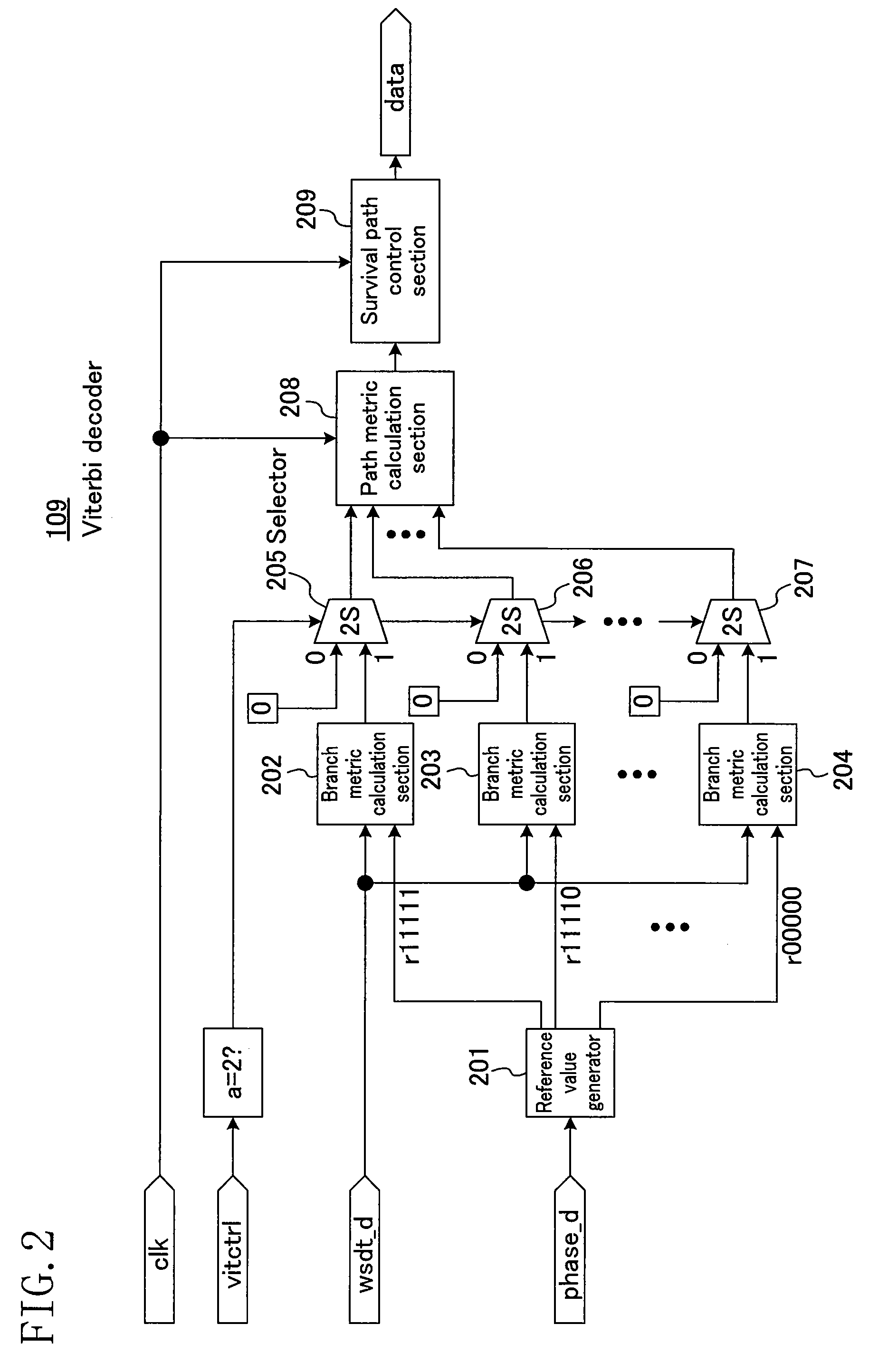
[0078]In the configuration of the Viterbi decoder 109′ illustrated in FIG. 4, the vitctrl signal shown in FIG. 2 is used as an undersampling signal, while an oversampling signal (a second selection signal) indicating the occurrence of oversampling of recorded data is input, and when this oversampling signal is received, branch metric calculation sections 202 to 204, a path metric calculation section 208, and a survival path control section 209 stop operating so as to change the branch metric calculation method, the path metric calculation method, and the data signal calculation method therein.
[0079]Hence, in this embodiment, proper operation is ensured not only when the recorded data is undersampled but also when oversampled.
third embodiment
[0080]Next, a third embodiment of the present invention will be described.
[0081]FIG. 5 illustrates the internal configuration of a Viterbi decoder 109″, which is an information reproduction apparatus according to the third embodiment of the present invention. In the second embodiment, the oversampling signal, and the undersampling signal (the vitctrl signal) from the FIFO 108 are input. In this embodiment, the Viterbi decoder 109″ is configured so as to receive a vitctrl signal (a Viterbi decoding control signal) alone and generate an oversampling signal.
[0082]To be specific, in FIG. 5, a controller 300 is added, which receives the vitctrl signal from the FIFO 108 and generates an undersampling signal and an oversampling signal. In view of the fact that the vitctrl signal from the FIFO 108 changes in value from 1 to 2 as described above when undersampling occurs, and changes in the opposite way from 1 to 0 when oversampling occurs, the controller 300 is configured so as to include a...
PUM
 Abstract
Description
Claims
Application Information
 - R&D
- Intellectual Property
- Life Sciences
- Materials
- Tech Scout
- Unparalleled Data Quality
- Higher Quality Content
- 60% Fewer Hallucinations
Browse by: Latest US Patents, China's latest patents, Technical Efficacy Thesaurus, Application Domain, Technology Topic, Popular Technical Reports.
© 2025 PatSnap. All rights reserved.Legal|Privacy policy|Modern Slavery Act Transparency Statement|Sitemap|About US| Contact US: help@patsnap.com