
Flexible phased array antennas

a phased array, flexible technology, applied in the direction of antennas, antenna adaptation in movable bodies, electrical equipment, etc., can solve the problems of negative drag on the platform, complicated antenna integration with the platform, and increase the associated cost of producing electronics assemblies

Inactive Publication Date: 2010-07-15
THE BOEING CO
View PDF11 Cites 28 Cited by
  • Summary
  • Abstract
  • Description
  • Claims
  • Application Information

AI Technical Summary

Benefits of technology

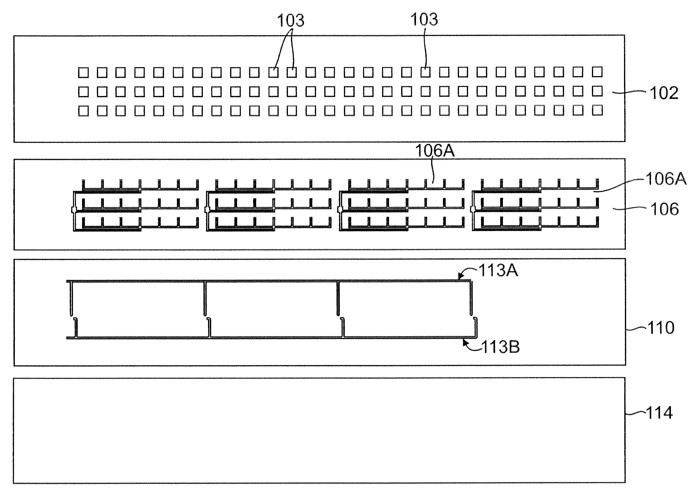
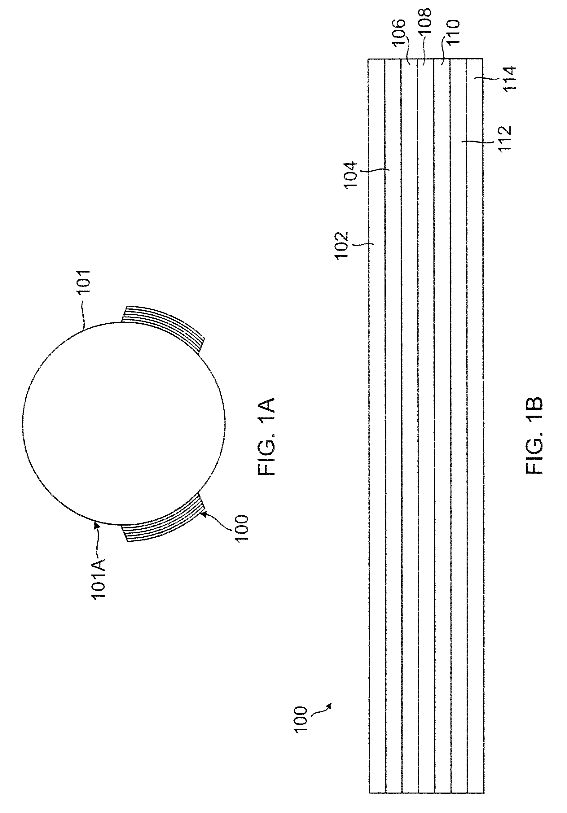
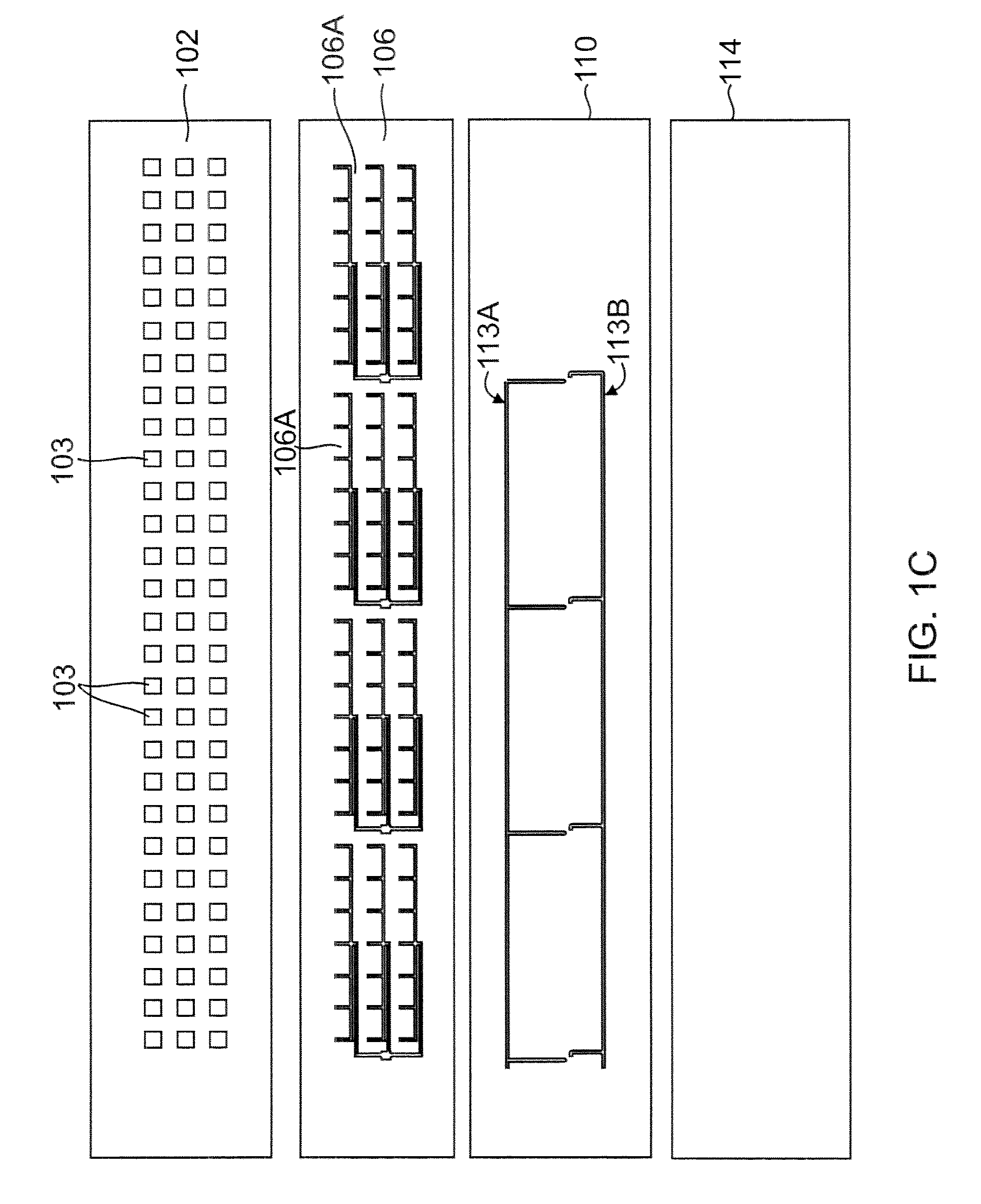
[0008]In one embodiment, a phased array antenna (PAA) is provided. The PAA includes a plurality of layers fabricated using an additive process such that the P conforms to a curvilinear surface. The plurality of layers include: a radiating layer placed on a first surface of a first dielectric layer; a feed layer ope...

Problems solved by technology

Due to the rigidity, the phased array antennas do not conform to a curvilinear surface of a platform and generally protrude out causing negative drag on the platform.
The thick structure also complicates antenna integration with the platform, and increases the associated cost of producing electronics assemblies that are generally preformed to a platform's outer contour.
Conventional phased array antennas fail to provide such characteristics.

Method used


Image

  • Flexible phased array antennas
  • Flexible phased array antennas
  • Flexible phased array antennas

Examples


Embodiment Construction

[0018]Phased array antennas (may also referred to as “PAA”) are widely used in radar systems and communication systems due to the added capability that results from electronically controlled phase shifters provided behind each radiating element. PAAs are typically mounted on a platform that communicates with a satellite or ground station, or that acts as the antenna for a radar system. Platforms (may also be referred to as “vehicles”) include aircrafts, helicopters, satellites, automobiles and any terrestrial or airborne vehicle. For purposes of this disclosure, phased array antennas mounted on fuselage of air vehicles are discussed. It is within the scope of the disclosure to use phased array antenna on any type of vehicle.

[0019]PAAs may include a plurality of layers, each layer performing a certain function (structural, electrical, signal, or any other function). The layers may be placed in different ways, depending on how the PAA is used. Furthermore, various topologies and vario...


PUM

PropertyMeasurementUnit
Dielectric polarization enthalpyaaaaaaaaaa
Poweraaaaaaaaaa
Flexibilityaaaaaaaaaa

Abstract

A phased array antenna (PAA) is provided. The PAA includes a plurality of layers fabricated using an additive process such that the PAA conforms to a curvilinear surface. The plurality of layers include: a radiating layer placed on a first surface of a first dielectric layer; a feed layer operationally coupled to a second surface of the first dielectric layer; and a second dielectric layer having a first surface operationally coupled a power and control layer and a second surface operationally coupled to a ground layer. An adhesive layer operationally couples the feed layer to the power and control layer.

Description

BACKGROUND[0001]1. Technical Field[0002]The present disclosure relates to phased array antennas.[0003]2. Related Art[0004]Phased array antennas are commonly used in radar systems and communication applications for airborne or terrestrial platforms. Phased array antennas typically include a plurality of antennas. A plurality of signals is sent to the plurality of antennas. To selectively reinforce the effective radiation pattern of the antenna array, the relative phase of the signals is varied.[0005]Phased array antennas are generally mounted on a platform that communicates with a satellite or ground station, or as illuminator and receiver in radar sensing applications. Platforms (may also be referred to as “vehicles”) include aircrafts, helicopters, satellites, automobiles and any terrestrial or airborne vehicle.[0006]Currently, phased array antennas are commonly assembled as monolithic structures. These structures frequently take the form of multilayer printed circuit boards that a...

Claims


Application Information

Patent Timeline
IPC IPC(8): H01Q21/00H01P11/00
CPCH01Q1/28H01Q3/26Y10T29/49018H01Q21/20H01Q21/065H01Q21/00
Inventor SEGO, DANIEL J.BANKS, DAVID L.URCIA, MANNY S.
Owner THE BOEING CO
Learn More