Method and device for explosion forming
a technology of explosive forming and forming method, which is applied in the direction of blasting, manufacturing tools, shaping tools, etc., can solve the problems of not being able to gain acceptance in the practice of mass production, the shortest possible setup time must be achieved repeatedly, etc., and achieve good sealing properties, good stability, and good cooling performance
- Summary
- Abstract
- Description
- Claims
- Application Information
AI Technical Summary
Benefits of technology
Problems solved by technology
Method used
Image
Examples
first embodiment
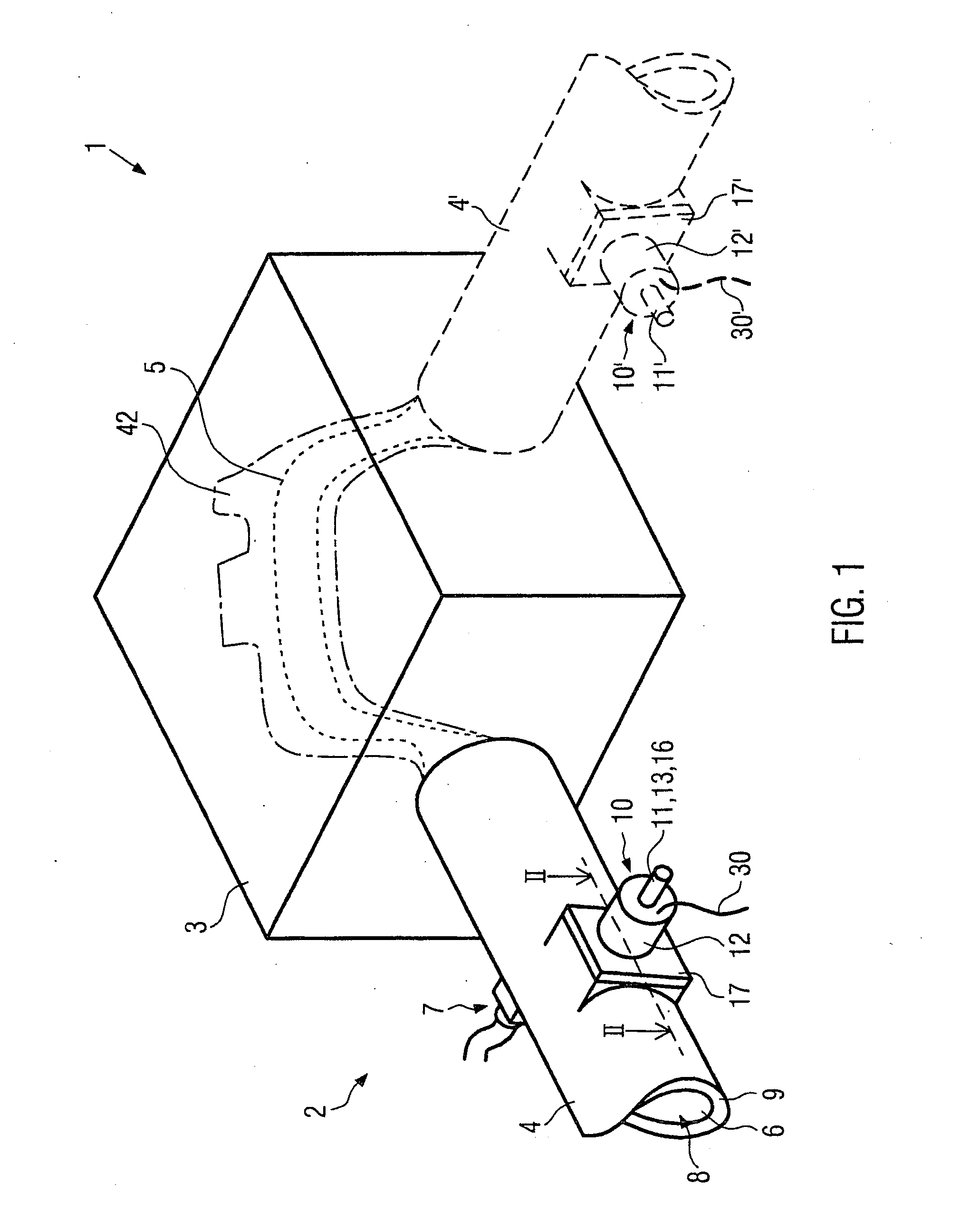
[0045]FIG. 1 shows a perspective view of a device for explosive forming according to the invention. The device 1 has a multipart die 2 with a forming device 3 and an ignition tube 4. The forming device 3 has a cavity 42 corresponding to the later work piece shape, which is indicated here with a dash-dot line. A work piece 5, indicated by a dotted line, is arranged in cavity 42.
[0046]The ignition tube 4 is made from a poorly heat-conducting material or only moderately heat-conducting material, like 1.4301 steel, and has an explosion chamber 6 in its interior. In the assembled state of the multipart die 2 shown here, the explosion chamber 6 is connected to cavity 42 in the forming device 3.
[0047]The explosion chamber 6 of the ignition tube 4 can be filled with an explosive 8 via a connection 7. In this embodiment of the invention, the explosive 8 is an explosive gas mixture, namely, oxyhydrogen gas. As an alternative, depending on the application, any different explosives, also fluids...
second embodiment
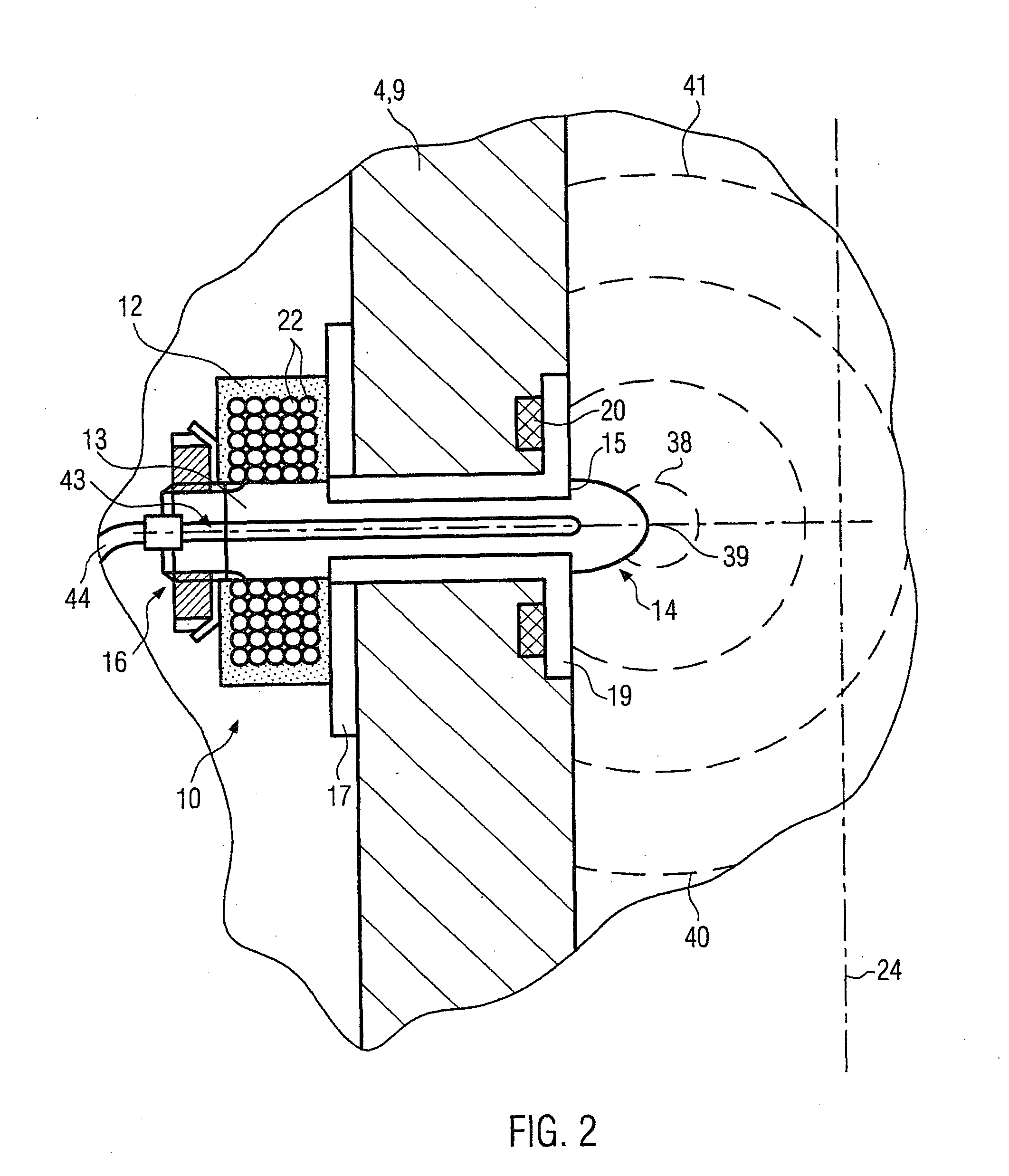
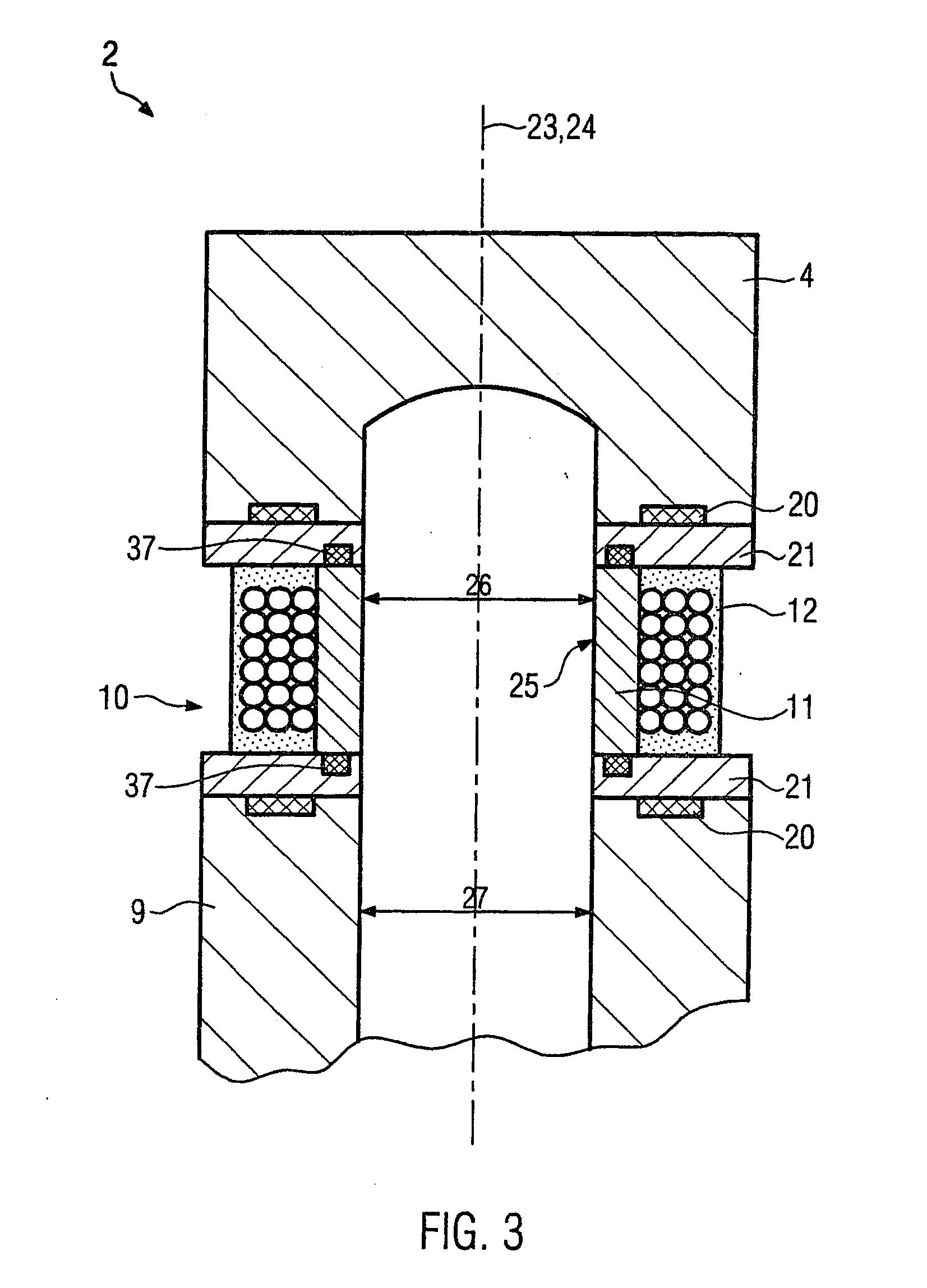
[0057]FIG. 3 shows a section through an induction element 10 according to the invention. The reference numbers used in FIG. 3 refer to the same parts as in FIGS. 1 and 2, so that the description of FIGS. 1 and 2 is referred to in this respect.
[0058]The induction element 10 is arranged here approximately in annular fashion around explosion chamber 6. It also has an ignition device 11 in this embodiment, a coil arrangement 12, as well as insulators 21. The induction element 10 is also arranged here with a seal 20 in die 2 and wall 9 of ignition tube 4, which seals the explosion chamber 6 relative to the surroundings.
[0059]The ignition device 11 in this embodiment of the invention is designed approximately in the form of a sleeve and arranged in annular fashion around explosion chamber 6. The longitudinal axis 23 of ignition device 11 then coincides approximately with the longitudinal axis 24 of explosion chamber 6.
[0060]The internal surface 25 of ignition device 11 facing explosion ch...
third embodiment
[0065]FIG. 4 shows a section through an induction element according to the invention. The reference numbers used in FIG. 4 refer to the same parts as in FIGS. 1 to 3, so that FIGS. 1 to 3 are referred to in this respect.
[0066]The induction element 10 in FIG. 4 is also arranged in wall 9 of ignition tube 4 via a copper-beryllium seal 20. The ignition device 11 is designed here with relatively small dimensions as a heating point 28. The heating point 28 in this embodiment has an approximately round, disk-like shape with relatively small diameter. However, it need not necessarily have this shape. In other embodiments of the invention, the heating point 28 can also be angled, oval or of any other shape.
[0067]The inner surface 25 of ignition device 11 and the heating point 28 facing the explosion chamber also runs in this embodiment approximately flush with wall 9. As an alternative, the heating point 28 could also extend, at least on areas, into explosion chamber 6. For example, the inn...
PUM
| Property | Measurement | Unit |
|---|---|---|
| diameter | aaaaa | aaaaa |
| diameter | aaaaa | aaaaa |
| diameter | aaaaa | aaaaa |
Abstract
Description
Claims
Application Information
 - R&D
- Intellectual Property
- Life Sciences
- Materials
- Tech Scout
- Unparalleled Data Quality
- Higher Quality Content
- 60% Fewer Hallucinations
Browse by: Latest US Patents, China's latest patents, Technical Efficacy Thesaurus, Application Domain, Technology Topic, Popular Technical Reports.
© 2025 PatSnap. All rights reserved.Legal|Privacy policy|Modern Slavery Act Transparency Statement|Sitemap|About US| Contact US: help@patsnap.com


