
System for Detection of Underwater Objects

a detection system and object technology, applied in the direction of burglar alarm short radiation actuation, burglar alarm electric actuation, instruments, etc., can solve the problem that the detection of objects underwater has been difficult to solve, the technique dependent on a reflected signal is not usually viable underwater, and the received signal is usually too weak to be detected at useful ranges, etc., to achieve the effect of sufficient range, resolution and speed

Inactive Publication Date: 2010-07-08
WIRELESS FIBER SYST
View PDF6 Cites 8 Cited by
  • Summary
  • Abstract
  • Description
  • Claims
  • Application Information

AI Technical Summary

Benefits of technology

[0007]The present invention relates to methods and systems for implementing a multi-span fence network. The spans may operate simultaneously. Using multiple spans allows the area to be protected to be fully enclosed or to greatly extend the range of monitored area by concatenation of fence spans. Multi-element fence networks also improve the ability to define the location of a detected object since detection will usually be limited to detecting the object's presence within a defined span.
[0010]The system provides sufficient range, resolution and speed to be able to protect assets from undetected approach underwater. It incorporates features to allow many transducer pairs to be used so that an extended area can be covered, allowing the object to be located within defined zones.

Problems solved by technology

In typical defence situations radar and related systems are used for discovering the existence of objects, which may be regarded as undesirable intruders.
In contrast to aerial or terrestrial conditions, detection of the presence of objects underwater has hitherto been a difficult problem to solve.
Techniques that are dependent on a reflected signal are not usually viable underwater.
This is because the attenuation of electromagnetic waves is very much greater in water than in air over both the forward and return paths, and the proportion of energy reflected is very small, so that the received signal is usually too weak to be detected at useful ranges.
This is particularly true for seawater, whose conductivity results in still greater attenuation than relatively fresh water.
Although lower frequencies can provide reduced attenuation, there are inherent physical difficulties, which in practice render insurmountable the launching of signals with sufficient energy at necessary low frequencies.
In particular, the presence of antennas above water may prevent the system being covert and make it liable to avoidance or sabotage.
In addition, the requirement for a reference air path introduces undesirable complications, such as the susceptibility of that reference air path to disturbance by aerial or surface objects such as passing ships.
Also, only a limited detection barrier of modest extent can be provided.

Method used


Image

  • System for Detection of Underwater Objects
  • System for Detection of Underwater Objects
  • System for Detection of Underwater Objects

Examples


Embodiment Construction

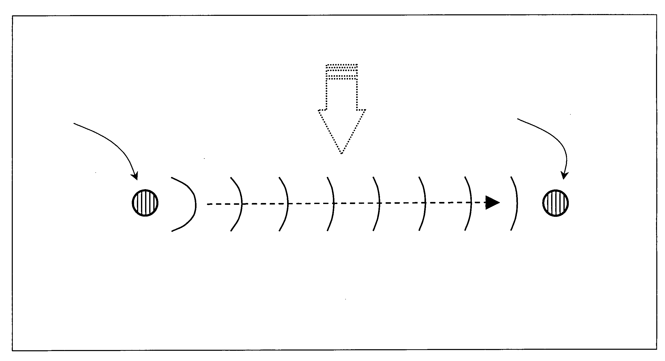
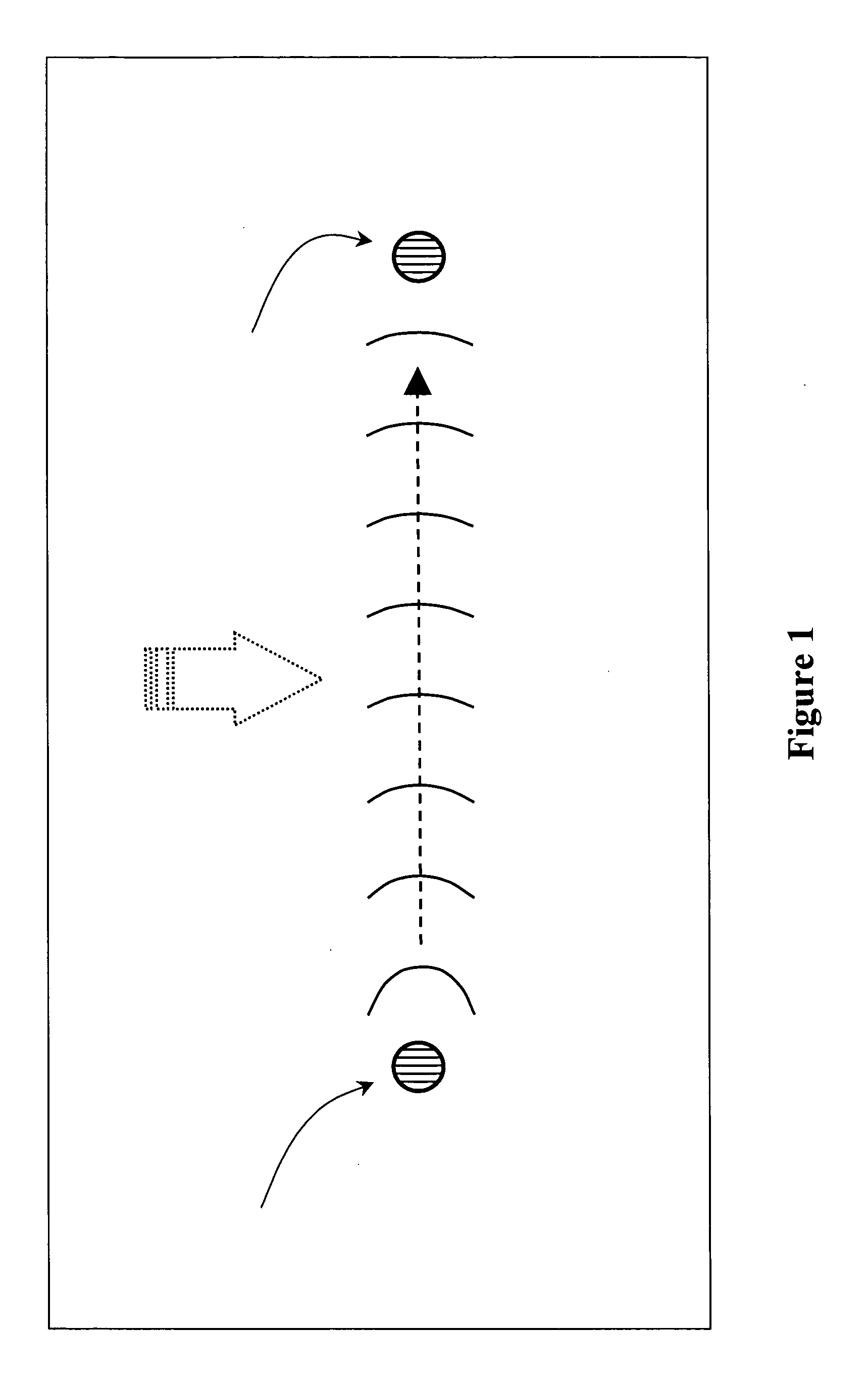
[0025]FIG. 1 shows one span of a multi-span security fence that has a transmitter with a transmit antenna 1, which is submerged in water, and a receiver with a receive antenna 2, also submerged. The region between the transmitter and receiver forms an elongated fence 3. The antenna may be of any suitable form, for example a magnetic coupled antenna, preferably based on loops or solenoids. The solenoid may be formed around a high magnetic permeability material. The insulated antenna may be surrounded with a low conductivity material with permittivity matched to that of the propagation medium e.g. distilled water. A signal emanating from the transmit antenna 1 passes through the region of the elongated fence 3 and is detected by the receive antenna 2. The transmitter operates continuously. By monitoring the received signal, perturbations or changes caused by the presence of an intruder 4 can be detected.

[0026]It will be understood that the wave does not propagate along a direct narrow...


PUM


Abstract

An underwater detection system comprising: at least one transmitter (14) for transmitting electromagnetic and / or magneto-inductive signals through water; at least one receiver (15, 16); means for monitoring a signal received from the transmitter (14), and means for using the monitored signal both as a reference and to identify any change or changes in the received signal to infer the presence of an interposing object.

Description

INTRODUCTION[0001]The present invention relates to a system and method for detecting the presence of underwater objects, which may infiltrate the region of a security boundary or virtual fence.BACKGROUND[0002]In air, electromagnetic waves are well known in various radar systems and similar applications for locating target objects. Electromagnetic energy is typically directed from a transmitter towards the vicinity of a potential target object and any reflected signal is taken to result from the presence of an object. Moreover, the position coordinates of the target can be inferred from the angular direction of return of the signal and the radial range from its return delay. Transmitter and receiver are usually co-located, but need not be provided they are cooperative and synchronised with each other. In typical defence situations radar and related systems are used for discovering the existence of objects, which may be regarded as undesirable intruders.[0003]In contrast to aerial or ...

Claims


Application Information

Patent Timeline
Patent Type & Authority Applications(United States)
IPC IPC(8): G08B13/24
CPCG01V3/12Y02A90/344G08B13/24G08B13/187Y02A90/30G08B13/2491G08B13/18
Inventor RHODES, MARKHYLAND, BRENDANBALLANTYNE, ALEXANDER
Owner WIRELESS FIBER SYST
Learn More