
Transient energy systems and methods for use of the same

a technology of energy systems and energy systems, applied in the field of transient energy systems, can solve the problems of poor reliability of batteries, large storage space, and high maintenance costs, and achieve the effects of reducing bearing load, increasing bearing life, and reducing bearing load

Inactive Publication Date: 2010-07-08
PILLER USA INC
View PDF49 Cites 10 Cited by
  • Summary
  • Abstract
  • Description
  • Claims
  • Application Information

AI Technical Summary

Benefits of technology

The optimized system reduces physical size, standby power consumption, and inductance, enabling quick switching between motoring and generating modes while extending bearing life and reducing costs, thus effectively addressing the inefficiencies of conventional systems.

Problems solved by technology

Batteries have poor reliability, are bulky (thus requiring substantial storage space), are expensive to maintain, and contain environmentally damaging chemicals.
Ultra-capacitors are expensive and their development has yet to achieve economies of scale which would permit their widespread use.
A disadvantage of such flywheel systems is that they become relatively large (thereby occupying substantial floor space), heavy and costly, in applications where longer runtimes are desired.
Because interruptions in the supply of power from a primary power source are relatively rare, the need for transient systems to supply power on demand may occur only a few times during the life of such systems.
However, when backup power is needed, the demands on the transient systems are high.
Some of the components within these systems can be highly customized and require manufacturing methods that are not widely used in industry thereby increasing cost.
Another type of system may be used to generate power, but is not conducive to transient power generation, includes conventional induction motor / generators that are driven by a prime mover (e.g., engine, wind, water, etc.) to generate power.
As such, the induction motor / generator is constructed to handle thermal and electrical limits for its power rating, resulting in larger sizing (and associated higher cost) and limited ability to rapidly transition from a motor mode to generator mode.

Method used


Image

  • Transient energy systems and methods for use of the same
  • Transient energy systems and methods for use of the same
  • Transient energy systems and methods for use of the same

Examples


Embodiment Construction

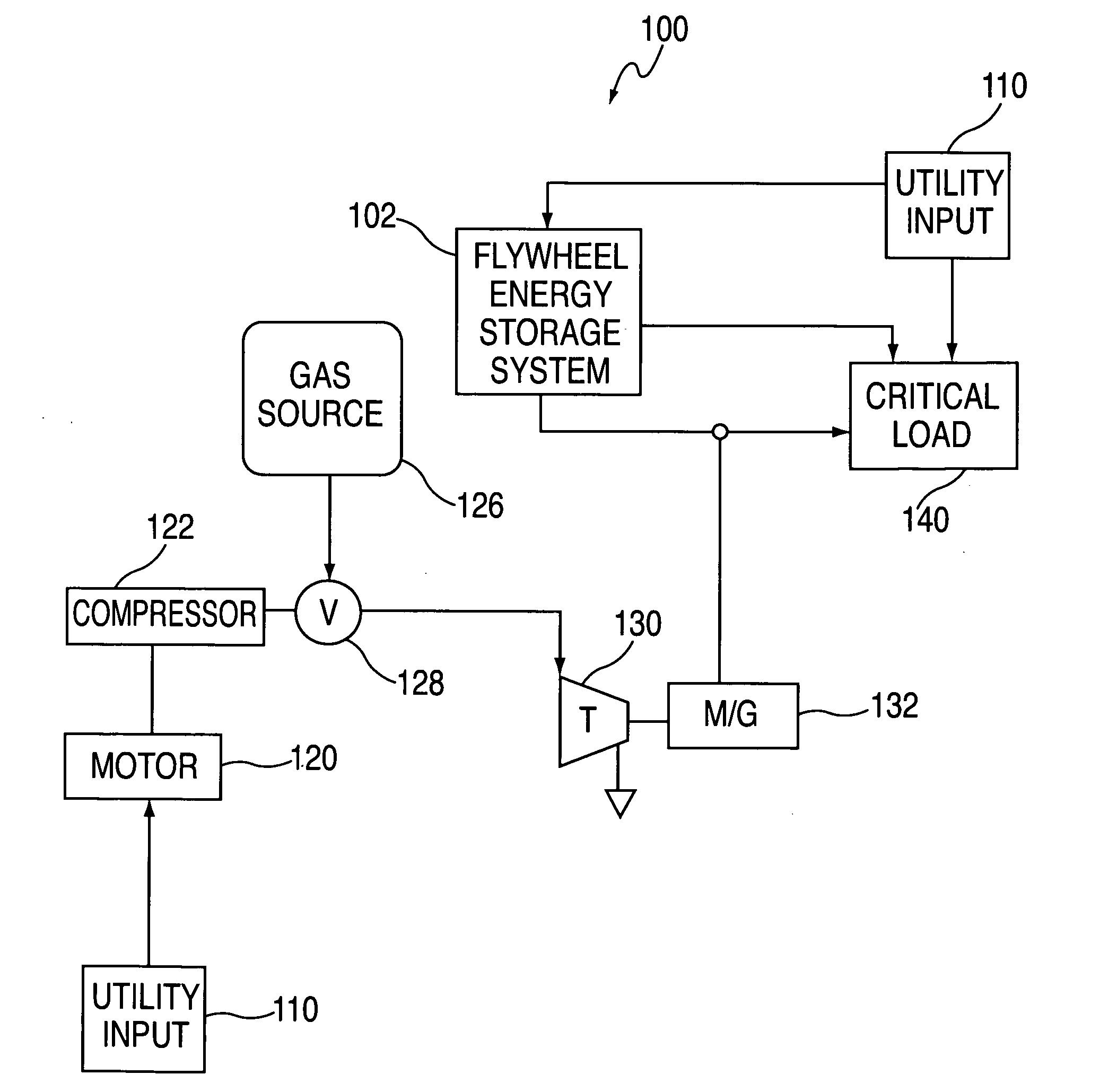
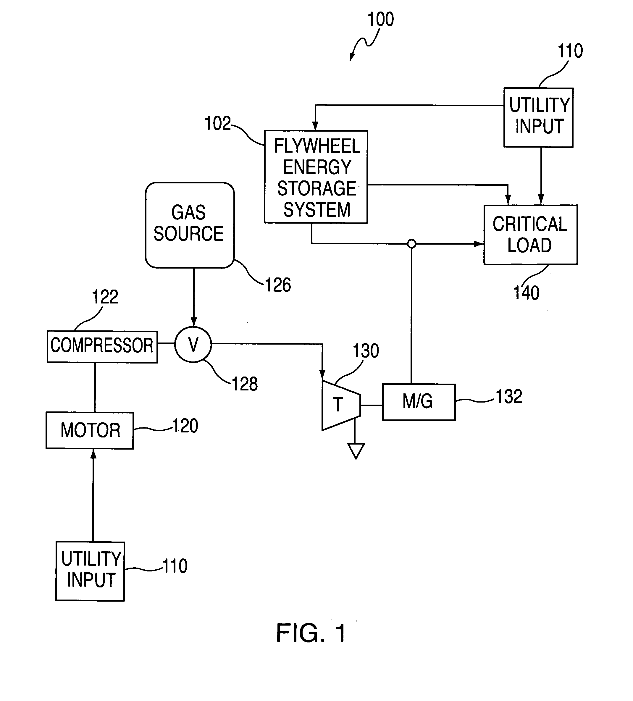
[0053]FIG. 1 shows a block diagram of a compressed air storage (CAS) backup energy system 100, including a flywheel energy storage system in accordance with the present invention, for providing backup power to a load. Backup energy system 100 includes utility input 110 which supplies power to critical load 140 during normal operating conditions. Persons skilled in the art will appreciate that utility input 110 may be any suitable type of primary power source. As illustrated in FIG. 1, backup energy system 100 includes a flywheel energy system 102 according to the principles of the present invention integrated with the components of a CAS system in order to provide backup power to critical load 140. Backup energy system 100 includes motor 120, compressor 122, gas source 126 (e.g., pressure tank), valve 128, turbine 130 and electrical machine 132.

[0054]During normal operating conditions, utility input 110 supplies critical load 140 with power. Utility power 110 also provides bridging ...


PUM


Abstract

This disclosure relates to transient energy systems for supplying power to a load substantially instantaneously on demand. Transient energy systems may include a flywheel coupled the rotor of an induction motor generator. One embodiment of the disclosure refers to systems and methods for reducing loads on a bearing in a transient energy system. In another embodiment, the disclosure refers to an induction motor generator that is optimized for high power transient power generation, yet low power motor operation. Yet another embodiment of the disclosure refers to using a flywheel as a drag pump to cool components of a transient energy system. In yet another embodiment, a slip control scheme is discussed for regulating a DC bus. In yet a further embodiment of the disclosure a method is provided for reducing unnecessary turbine starts by making turbine start a function of the rotational velocity of a flywheel.

Description

BACKGROUND OF THE DISCLOSURE[0001]This relates to transient energy systems for supplying power to a load substantially instantaneously on demand. More particularly, this relates to flywheel energy storage / systems constructed with an induction motor-generator.[0002]There are many different types of transient systems, including, for example, batteries, ultra-capacitors, and flywheel energy storage systems, all of which are capable of providing power substantially immediately on demand. Batteries have poor reliability, are bulky (thus requiring substantial storage space), are expensive to maintain, and contain environmentally damaging chemicals. Ultra-capacitors are expensive and their development has yet to achieve economies of scale which would permit their widespread use. An example of a flywheel energy storage system includes the relatively high mass flywheel type of system. In this type of flywheel energy system, the flywheel is contained in an airtight container under vacuum to r...

Claims


Application Information

Patent Timeline
Patent Type & Authority Applications(United States)
IPC IPC(8): H02J3/30
CPCF16C25/08F16C39/06H02J9/066H02K7/025H02K7/083H02K7/09H02P9/00H02P2207/01Y02E60/16Y10T307/522H05K7/1498Y04S20/20Y02B70/30
Inventor PERKINS, DAVID E.
Owner PILLER USA INC
Learn More