Valve device of an application device for applying fluid to a substrate, and applicator

a technology of fluid application device and valve device, which is applied in the direction of valve housing, liquid transfer device, instruments, etc., can solve the problems of requiring considerable adjustment with separate micrometric measuring devices, affecting the accuracy of application, etc., to achieve the effect of easy removal, precise adjustment and sensitive to damag

Active Publication Date: 2010-07-08
J ZIMMER MASCHENBAU GES
View PDF13 Cites 29 Cited by
  • Summary
  • Abstract
  • Description
  • Claims
  • Application Information

AI Technical Summary

Benefits of technology

[0008]The invention is therefore based on the aims of improving and simplifying the cleaning and maintenance of the application device and its valve devices. In particular, maintenance and cleaning are to be capable of being performed effectively and easily while maintaining adjustment settings of the valve nozzles.
[0011]The valve device according to the present invention with electromagnetic device and the application device according to the present invention equipped with electromagnetic valves afford, particularly also in conjunction with a cleaning valve device of the application device, advantages for cleaning the valve fluid ducts between the distributing fluid chamber and the application valve nozzles. When the valve housing is removed, not only does the mounting opening expose the valve piston for removal from the valve device, but also the fluid duct comprising the piston wall is exposed. The rectilinear valve fluid duct which remains free from flow corners ensures excellent flushing. Flow shadows which arise in known application devices due to undercuts, dead corners, areas with slow flow speeds or the like, are avoided. Harmful air bubbles are avoided, because particularly effective deaeration is achieved by the straight flow path running on the wall of the adjusting piston and the valve piston. With the application valve device in each case opened individually, the cleaning fluid cleans the path between the distributing fluid chamber and the valve seat or the valve nozzle arranged thereon, without the application device having to be dismantled. An important advantage here also lies in that the adjusting position of the valve piston set with the adjusting piston is maintained.
[0013]The valve nozzle forms part of the valve housing. A nozzle orifice is formed which, as such, covers the mounting opening and its edge from below, the valve housing with the nozzle being designed so as to form together a single part for handling. Advantageously, the nozzle forms on the piston side the valve seat. By simply exchanging the valve housing for a valve nozzle with different dimensions, different degrees of fineness and fluid quantities (ink quantities) can be obtained for application. An adjusting device is preferably formed by a screwed connection with fine thread. By screwing in and unscrewing the adjusting piston, the fine distance with respect to the valve piston and hence the desired fine piston stroke can be adjusted precisely. The piston stroke directly affects the throughflow of the valve device, so that precise adjustment is particularly important for achieving uniform application, in particular a uniform printed image. With the nozzle construction according to the invention, adjustment of the stroke can take place during valve operation. Rotary adjustment of the adjusting piston results in a direct change in throughflow through the valve nozzle.
[0014]A further advantage lies in that, in particular after the distributing fluid chamber has been cleaned, the fluid duct between the distributing fluid chamber and the associated application nozzle can be cleaned by the fact that the detachably mounted valve housing designed as a nozzle orifice is removed in case of major contamination. The valve housing and the valve piston are easily removed and remounted on the nozzle side of the application device, that is, on the lower side of the device which forms the application side. Such partial dismounting may be necessary if a change of fluid is to be made, e.g. a change of colour. Unlike conventional application devices, valve bodies or wall parts are not dismounted. This is a considerable advantage, as the adjusting devices are very sensitive to damage. The slightest damage or refitting valve bodies or wall parts can already falsify adjustments within a range of a few micrometres. Flushing the distributing fluid chamber also covers the adjusting pistons for cleaning, without dismounting taking place on the upper / rear side of the application device.
[0015]The valve device according to the invention even in the single form achieves the result that, along the straight valve duct path between the supply fluid chamber and the valve nozzle, a straight longitudinal flow takes place. The longitudinal construction avoids flow shadows which would otherwise arise due to undercuts, dead corners, areas with slow flow speeds or the like. Hence not only can the single valve device, as already described, be cleaned particularly well by flushing through. Due to the longitudinal flow, the inner region of the electromagnetic device, namely a magnet coil which partly surrounds the adjusting piston and the valve piston, is effectively cooled as well. This has a favourable effect on the life of the valve device. Design and assembly of the valve device are particularly simple.
[0016]The single valve device already has the advantages which were mentioned in connection with the valve devices of the application device. In case of particularly major blockage, the valve housing can easily be removed. The mounting opening is so large that the valve piston likewise can easily be taken out. Hence the valve fluid duct or the common piston chamber which receives the valve piston and the adjusting piston opens towards the nozzle side, that is, downwards. By flushing with cleaning fluid under pressure, the valve fluid duct and the piston chamber are flushed through, and any particles of dirt present are flushed out downwards. The adjusting piston and the adjusting device are not dismounted. Adjustment settings can be retained, and they can be made precisely even during operation of the device, that is, during application.

Problems solved by technology

Contamination occurs in particular after an initial assembly.
But breakdowns due to deposits also occur while operation is ongoing.
After subsequent assembly, adjustment with considerable effort using separate micrometric measuring devices is necessary.

Method used


Image

  • Valve device of an application device for applying fluid to a substrate, and applicator
  • Valve device of an application device for applying fluid to a substrate, and applicator
  • Valve device of an application device for applying fluid to a substrate, and applicator

Examples


Embodiment Construction

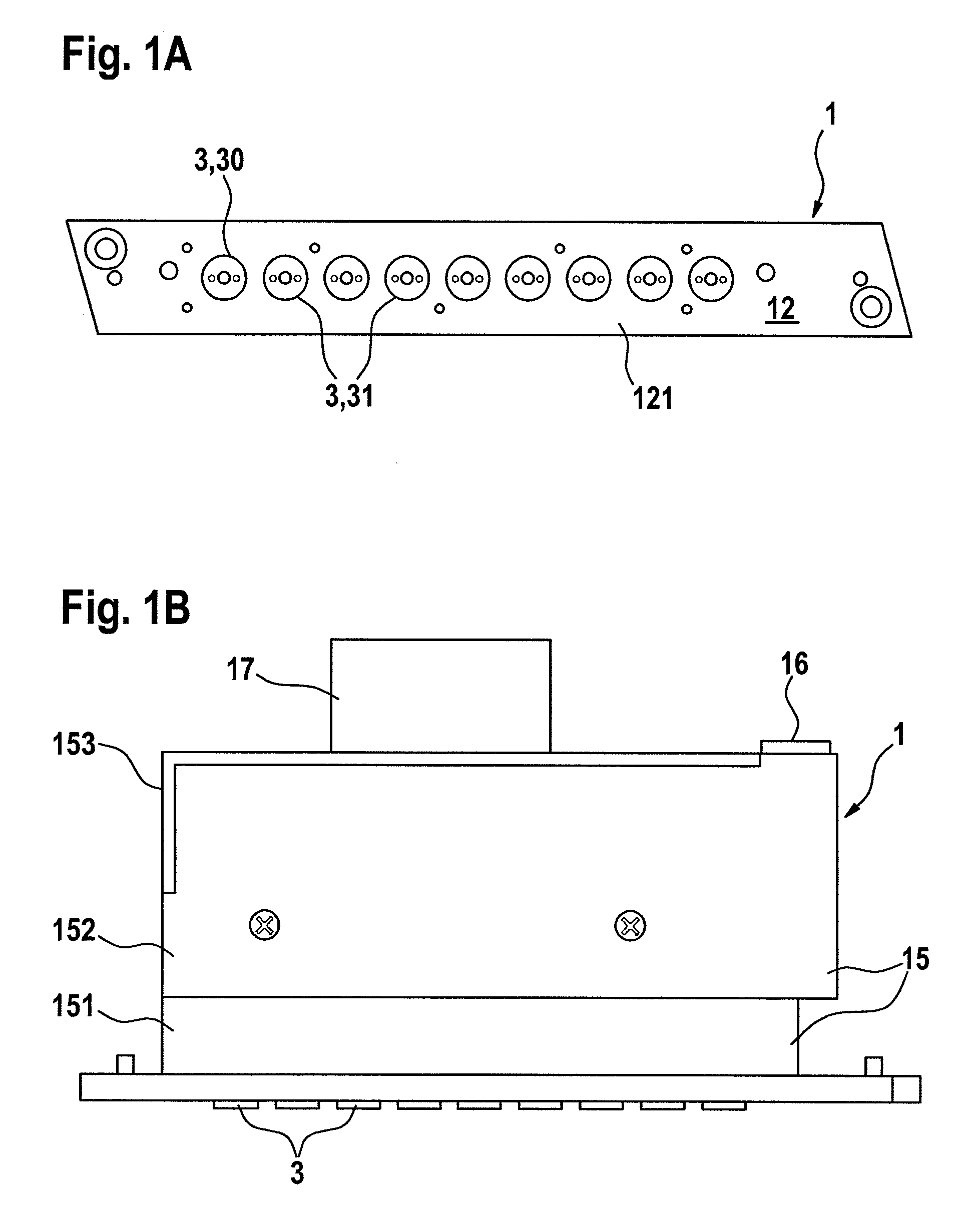
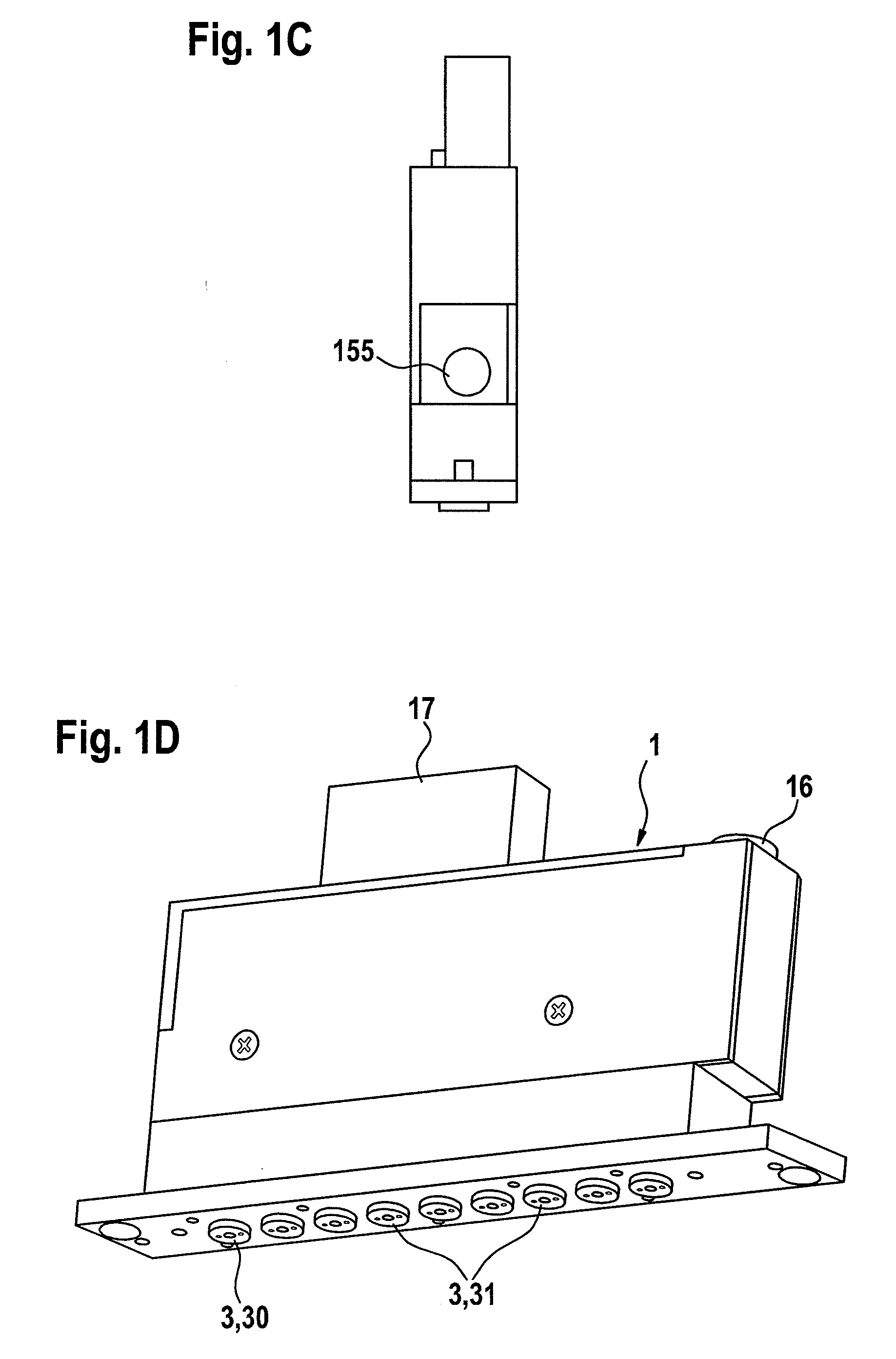
[0022]An application device according to the invention shown in FIGS. 1A to D comprises a box-like valve body 15 as a component of valve devices 2. The valve body is composed of a lower socket portion 151 and an upper cover portion 152. The lower portion 151 is closed by a narrow elongate nozzle plate 121 which receives valve nozzles 3 in a particular embodiment according to the invention. The valve nozzles 3 are arranged in a straight row on the nozzle / application side 12. On the opposite side, the application device 1 has an electrical plug-in connection 17 and a connecting opening 16 for application fluid. In the practical example the row of valve nozzles 3 is defined by eight application valve nozzles 31 and one cleaning valve nozzle 30 which closes the row of nozzles. The cleaning valve nozzle 30 is arranged at the end of the row of nozzles opposite the connecting opening 16.

[0023]As can be seen from the sectional view in FIG. 2, the valve body 15 is connected to an electronic ...


PUM


Abstract

A valve device of an application device for applying fluid to a substrate comprises a valve body, a valve housing with inner chamber and valve seat, a supply fluid chamber, an electromagnetic valve actuating device with valve piston and an adjusting piston. The valve nozzle is detachably mounted on the nozzle side of the valve device. The valve device has a nozzle plate which closes the valve body at the bottom on the nozzle side, with mounting opening for the valve piston. The valve housing is designed in the form of a nozzle orifice which is a closure member that can be fitted on the mounting opening from below and removed. The valve nozzle forms part of the valve housing. The valve piston is exposed through the mounting opening of the nozzle plate for removal and fitting when the closure member is removed. The valve device is provided with at least one rectilinear fluid duct that connects the supply fluid chamber to the valve seat. The valve piston and part of the adjusting piston together form a wall of the straight fluid duct which, when the nozzle orifice closure member is removed, is exposed for cleaning through the mounting opening. An application device comprises the valve devices arranged in a row.

Description

[0001]This application is a 35 U.S.C. §371 filing of International Patent Application No. PCT / EP2008 / 004123 filed May 20, 2008, designating the United States and claiming the benefit of European Application No. 07090124.4 filed Jun. 14, 2007.BACKGROUND OF THE INVENTION[0002]The invention concerns a valve device of an application device for applying fluid to a substrate, comprising a valve body, a valve housing with associated valve nozzle for emission of the fluid under pressure, having an inner chamber which can admit fluid and a valve seat arranged there, a supply fluid chamber which can be subjected to fluid pressure, a fluid connection between supply fluid chamber and valve housing inner chamber, a valve actuating device which is formed by an electromagnetic device with valve piston movable back and forth against a return force and engaging in the valve seat for opening and closing the valve nozzle, and a piston stop which forms an adjusting piston and against which the valve pi...

Claims


Application Information

Patent Timeline
Patent Type & Authority Applications(United States)
IPC IPC(8): G01F11/00F16K31/02F16K51/00F16K27/00B05B9/04B65D88/54B67D3/00B05B15/55
CPCB05B1/20B05B1/3053B05C5/0279B05C5/0225B05B15/025B05B15/55
Inventor ACHRAINER, JOHANN
Owner J ZIMMER MASCHENBAU GES
Why Eureka
Try Eureka