Eureka AIR delivers breakthrough ideas for toughest innovation challenges, trusted by R&D personnel around the world.

Modular brake caliper

Inactive Publication Date: 2010-07-08
BIGGS ROBERT
View PDF14 Cites 29 Cited by
  • Summary
  • Abstract
  • Description
  • Claims
  • Application Information

AI Technical Summary

Benefits of technology

[0008]The caliper assembly can further include a heat shield disposed upon the integral piston block and configured to reduce radiant heat transfer into the piston block and side bridge. The caliper assembly can further include a coating applied to one or more of the at least one top bridge, at least one side bridge with an integral piston block, and at least one end bridge comprising the caliper assembly to prevent corrosion, reduce heat transfer, and increase lubricity. The caliper assembly can further include a means of attachment to interconnect the at least one top bridge, at least one side bridge with an integral piston block, and at least one end bridge comprising the caliper assembly.
[0029]This caliper assembly can include a heat shield disposed upon the piston block and configured to reduce radiant heat transfer into the piston block and side bridge. This caliper assembly can include a coating applied to one or more of the at least one top bridge, at least one side bridge, and at least one piston block comprising the caliper assembly to prevent corrosion, reduce heat transfer, and increase lubricity. This caliper assembly includes a means of attachment to interconnect the at least one top bridge, at least one side bridge, and at least one piston block comprising the caliper assembly.

Problems solved by technology

There is an ongoing challenge to maintain the integrity of brake calipers.
Maintaining strength, stiffness, and performance of such brake calipers with known methods often results in manufacturing complexity, increased cost, and complex geometry to achieve better stress optimization.

Method used


Image

  • Modular brake caliper
  • Modular brake caliper
  • Modular brake caliper

Examples


Embodiment Construction

[0054]Before describing the disclosed embodiments of this technology in detail, it is to be understood that the technology is not limited in its application to the details of the particular arrangement shown here since the technology described is capable of other embodiments. Also, the terminology used herein is for the purpose of description and not of limitation.

[0055]Standard performance brake calipers are made in two halves and bolted together. To improve strength, stiffness, and performance, brake calipers are made as mono-block assemblies. For example, caliper body and piston bores are machined from one piece. This creates manufacturing complexity and high cost. Further improvement on the mono-block technology has led to very complex machined caliper bodies to maximize strength.

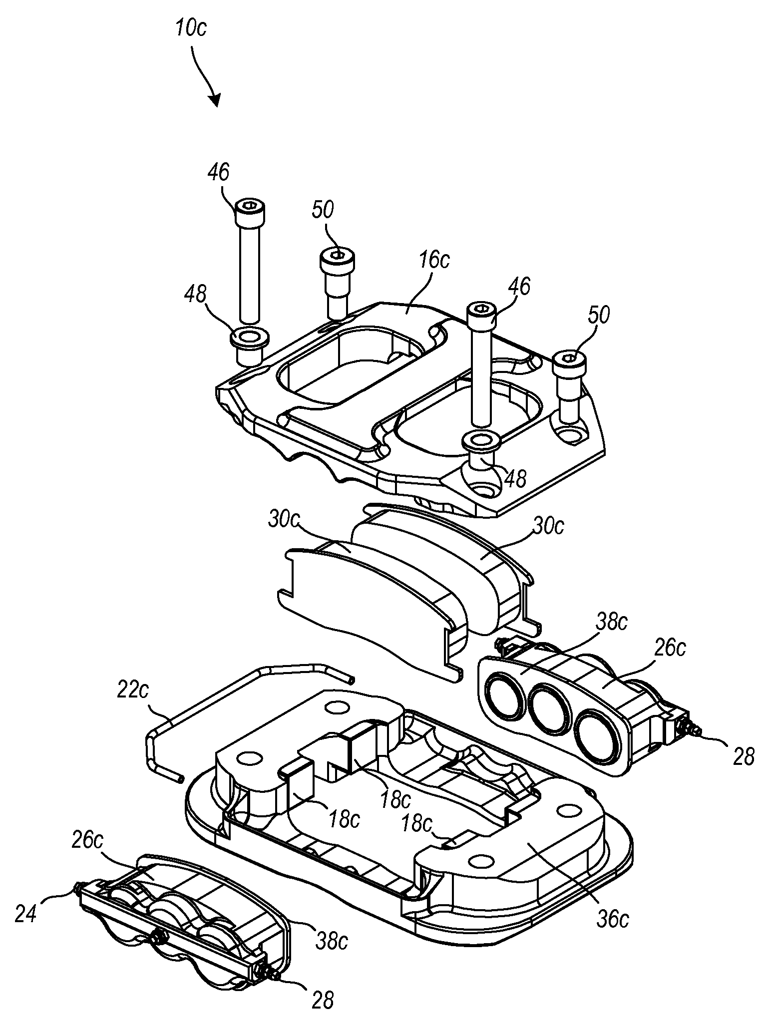
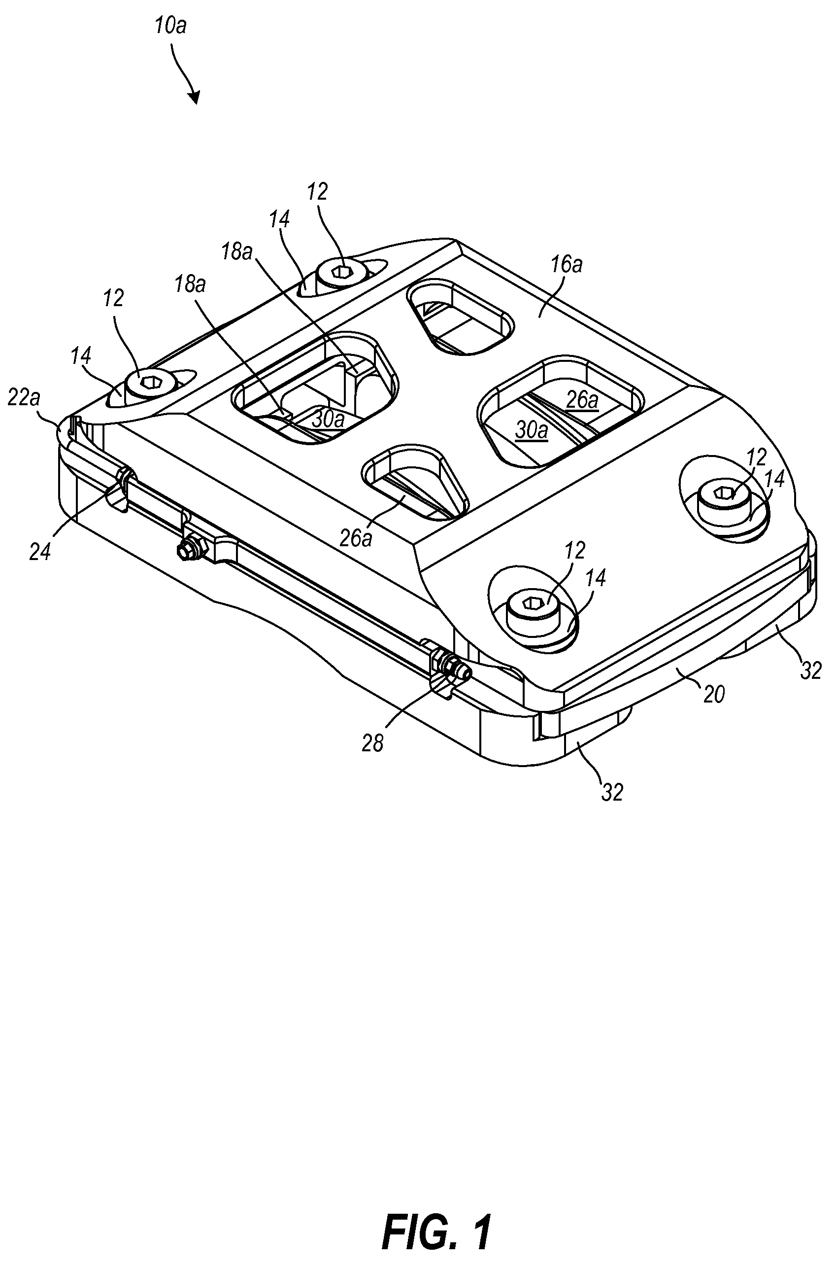
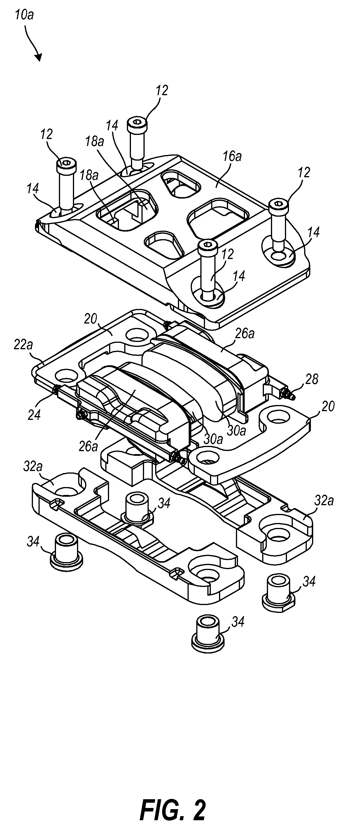
[0056]In various exemplary embodiments, the technology described herein provides a modular hydraulic brake caliper for use on automobile vehicles and motorcycles. The modular hydraulic brake caliper pro...


PUM


Abstract

In various exemplary embodiments, the technology described herein provides a modular hydraulic brake caliper for use on automobile vehicles and motorcycles. A modular hydraulic disc brake caliper housing to house a piston block assembly includes one or more top bridge configured to stiffen and strengthen a disc brake caliper. The housing includes one or more caliper body configured to stiffen and strengthen a modular hydraulic brake caliper assembly, to securely receive the top bridge and to restrain a piston block assembly, and is configured with or without the use of an integral piston. The housing can include at least one side bridge configured to stiffen and strengthen the modular hydraulic brake caliper assembly. The housing can include at least one end bridge configured to secure one side bridge to another and to the top bridge. A modular hydraulic disc brake caliper assembly, a disc brake assembly, and associated methods are disclosed.

Description

FIELD OF THE INVENTION[0001]The technology described herein relates generally to disc brake systems for automobile vehicles and motorcycles. More specifically, this technology relates to a modular brake caliper.BACKGROUND OF THE INVENTION[0002]In various applications, many automobile vehicles and motorcycles utilize disc brake systems. Disc brake systems have brake calipers. A brake caliper is an assembly which houses the brake pads and pistons. There is an ongoing challenge to maintain the integrity of brake calipers. By way of example, many brake calipers known in the art are mono-block assemblies, wherein the caliper body and piston bores are machined from one original piece. Maintaining strength, stiffness, and performance of such brake calipers with known methods often results in manufacturing complexity, increased cost, and complex geometry to achieve better stress optimization.[0003]A related patent known is U.S. Pat. No. 5,810,121, issued to Anger et al. on Sep. 22, 1998. Th...

Claims


Application Information

Patent Timeline
IPC IPC(8): F16D55/22
CPCF16D55/224F16D55/228F16D2055/002F16D2055/0091F16D2121/02
Inventor BIGGS, ROBERT
Owner BIGGS ROBERT
Why Eureka
Eureka Blog
Learn More