
Quick release device for faucets

a technology of quick release and faucet, which is applied in the direction of functional valve types, couplings, transportation and packaging, etc., can solve the problems of inconvenient removal and installation of conventional faucets, excessive remaining metals, and inhuman body harm, so as to prevent water leakage, save installation time, and be quick installed.

Inactive Publication Date: 2010-07-08
LONG TAI COPPER
View PDF13 Cites 11 Cited by
  • Summary
  • Abstract
  • Description
  • Claims
  • Application Information

AI Technical Summary

Benefits of technology

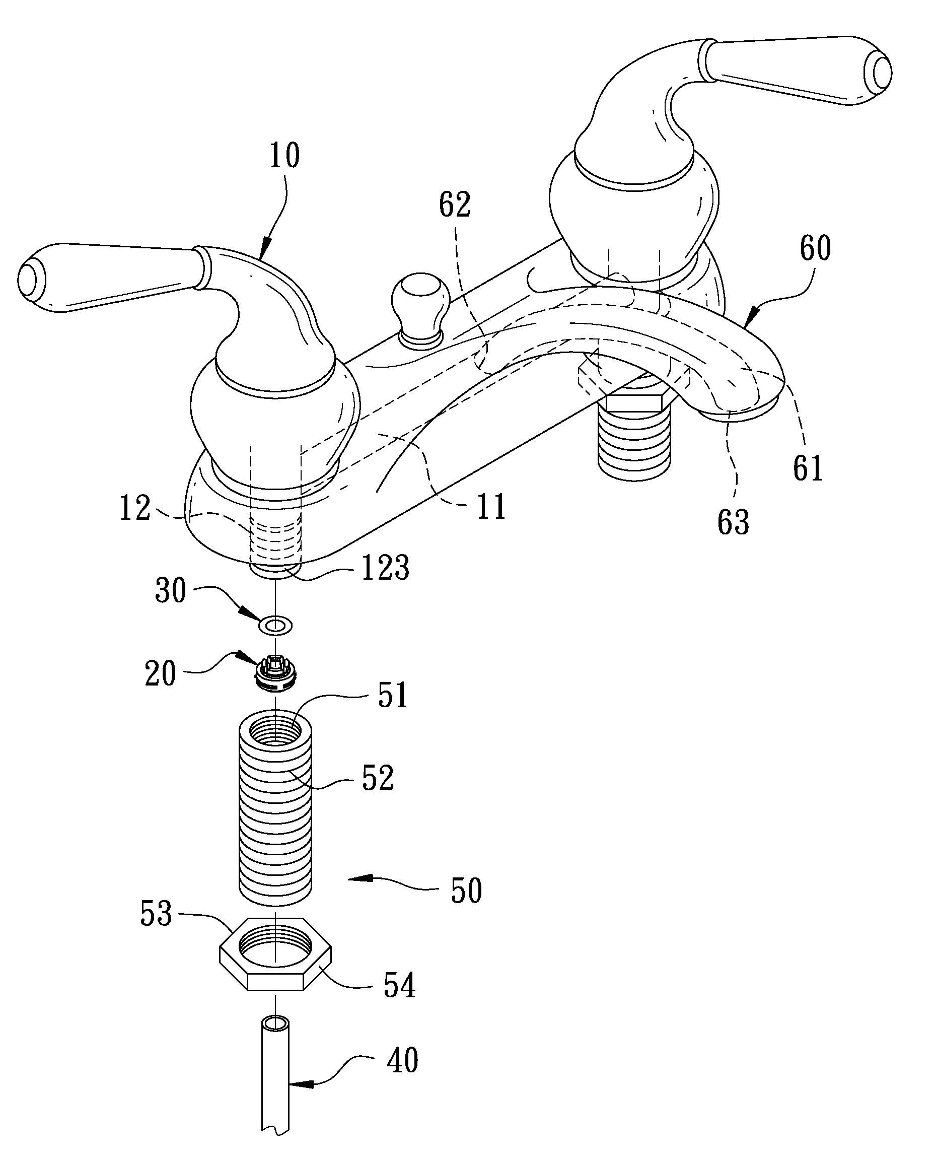
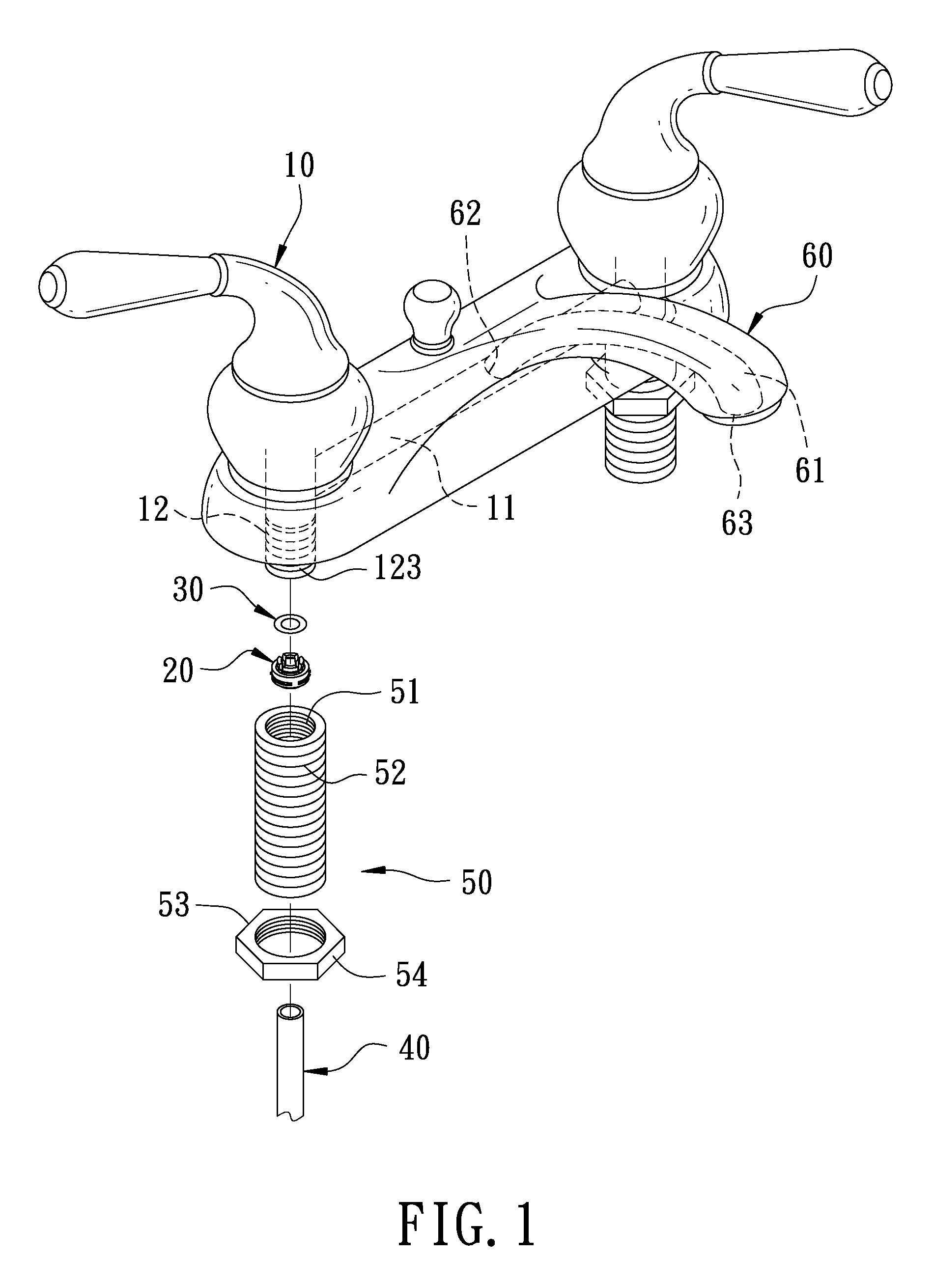
[0007]A quick release device for faucets according to this invention mainly comprises a valve and a quick release unit. The valve is connected to at least two passages through which water flows, at least one passage is formed with a concave joint slot the inner circumference of which is formed with a shift limit slot. The quick release joint group is correspondingly arranged in the joint slot, and a shift limit unit is provided around the outer circumference of quick release joint and may thereby fixed in the shift limit slot. A watertight unit is provided between the joint slot and the quick release joint group to prevent water leakage. A pipeline is provided that may be quickly installed on and removed from the quick release joint group.
[0008]Regarding the quick release device for faucets, only the pipeline passes through the quick release joint unit and the watertight unit for completion of installation, which saves installation time, reduces complicated installation steps, decreases the area where flowing water contacts the metal, and lower the metal precipitation.

Problems solved by technology

However, in the manner of spiral fixing, it takes more time and is inconvenient to remove and install the conventional faucet, and a tool is required for installation.
Further, in the valve, the water current and the metal surface contact area are larger; the larger the contact surface area is, the easier the metallic substances are brought; excessive remaining metals does harm to human body.

Method used


Image

  • Quick release device for faucets
  • Quick release device for faucets
  • Quick release device for faucets

Examples


Embodiment Construction

[0018]Now, the present invention will be described more specifically with reference to the following embodiments. It is to be noted that the following descriptions of preferred embodiments of this invention are presented herein for purpose of illustration and description only; it is not intended to be exhaustive or to be limited to the precise form disclosed.

[0019]With reference to FIGS. 1, 2, and 3 shown respectively as a partial 3D exploded perspective view of a lavatory faucet with two lever handles, a partial 3D exploded perspective view of a water inlet passage, and a 3D exploded view of a quick release joint unit, the lavatory faucet with two lever handles mainly comprises a faucet body 60, two valves 10, two quick release joint units 20, two watertight units 30, two water pipes 40, and two joint units 50.

[0020]A gateway 61 is formed in the faucet body 60, and a water inlet 62 and a water outlet 63 are formed at the outside of faucet body 60 that is opposite to two ends of the...


PUM


Abstract

A quick release device for faucets mainly includes a valve and a quick release unit. The valve is connected to at least two passages through which water flows, at least one passage is formed with a concave joint slot the inner circumference of which is formed with a shift limit slot. The quick release joint unit is oppositely arranged in the joint slot, and a shift limit unit is provided in the quick release joint and may be thereby fixed in the shift limit slot. A pipeline is provided that may be quickly installed on and removed from the quick release joint group. Thus, the installation time may be saved, the complicated installation steps may be reduced, and the area where flowing water contacts the metal may be decreased.

Description

BACKGROUND OF THE INVENTION[0001]1. Field of the Invention[0002]This invention relates to a quick release device for faucets.[0003]2. Description of the Related Art[0004]A conventional faucet is provided with a valve. The valve is connected to two passages the outer circumference of which is formed with threads that are used to spirally fix a water inlet pipeline and a water outlet pipeline, and the water outlet is controlled by the valve.[0005]However, in the manner of spiral fixing, it takes more time and is inconvenient to remove and install the conventional faucet, and a tool is required for installation. Further, in the valve, the water current and the metal surface contact area are larger; the larger the contact surface area is, the easier the metallic substances are brought; excessive remaining metals does harm to human body.[0006]Consequently, because of the technical defects of described above, the applicant keeps on carving unflaggingly through wholehearted experience and ...

Claims


Application Information

Patent Timeline
IPC IPC(8): F16K21/00
CPCE03C1/0403F16K19/006F16L37/0925Y10T137/598
Inventor WU, FAUCET
Owner LONG TAI COPPER
Learn More