
Pumping unit

a technology for oil and gas wells and pumping units, which is applied in the direction of positive displacement liquid engines, construction, etc., can solve the problems of mechanics being in dangerous positions, difficult to hoist the gear reducer up, and all components are very heavy, so as to achieve quick and economical replacement, high stroke speed, and high efficiency

Inactive Publication Date: 2010-07-08
NEW RIVER EQUIP
View PDF10 Cites 21 Cited by
  • Summary
  • Abstract
  • Description
  • Claims
  • Application Information

AI Technical Summary

Benefits of technology

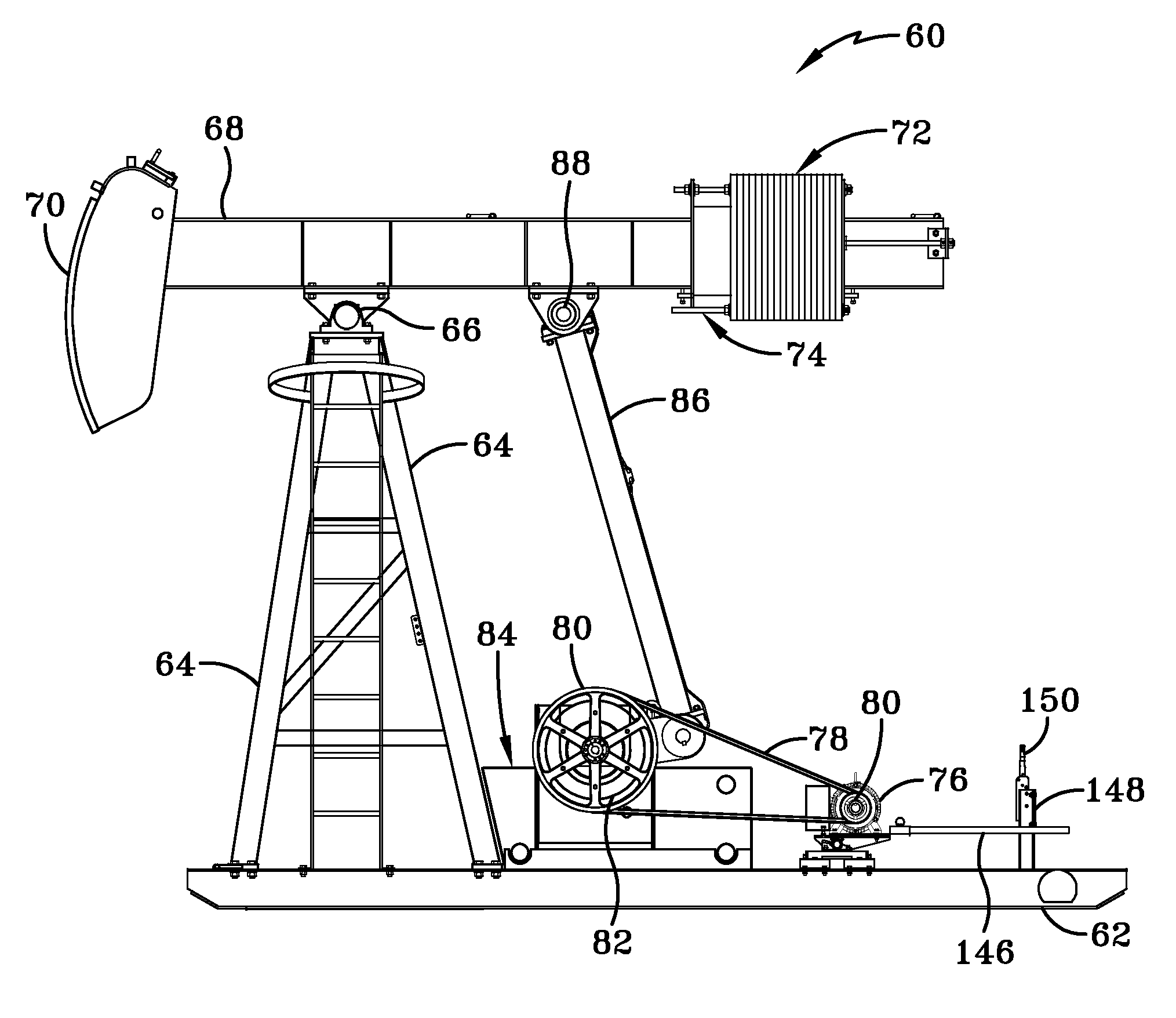
The present invention provides a pumping unit for removing fluid from a well that includes a crank system that supports the heavy loads of the walking beam and beam weights, and converts the rotational motion of the crank into reciprocating motion at the horse head, while being independent of the gear reducer. The gear reducer is only used for rotating the crank system, so it is not subject to the heavy loads of the walking beam and beam weights. The crank assembly is capable of being positively locked in position to secure the walking beam, beam weights, and pitman arms, and an improved bearing system is used throughout the crank system. The pumping unit includes an inexpensive gear reducer that can be easily replaced. The gear reducer has a deeper gear reduction ratio, and the stroke speed is as low as four spm. The pumping unit also includes an automatic belt tensioning system, an indefinite belt life, an improved balancing system, an integrated enclosure around the crank assembly, and a system to disengage the belts while applying a walking beam brake. These technical effects provide a more efficient, reliable, and economical pumping unit for removing fluid from a well.

Problems solved by technology

All of these components are very heavy and require the use of a lifting device or crane to remove.
However, because the walking beam and beam weights are directly above the gear reducer, it is difficult to hoist the gear reducer up due to interference between the hoist mechanism and the walking beam.
In either case, the mechanics find themselves in a position that may be dangerous due to its location directly under the heavy walking beam and beam weights.
The mechanics must use care to ensure that the chains and / or binders securing the walking beam in place are not accidentally or inadvertently released, since the beam and weights might undesirably swing down toward the gear reducer.
Other disadvantages of prior art pumping units are associated with the type of gear reducer that has been used in the prior art.
More particularly, the prior art gear reducer is an expensive, custom-built parallel gearbox that is mounted on the base of the pumping unit.
Such a construction makes the gearbox very expensive.
The custom-built parallel gearbox of the prior art is also undesirably time consuming and expensive to repair.
More particularly, when the gearbox is repaired in the field, multiple trips by mechanics typically are required.
The parts for the repair of the custom gearbox typically can only be purchased from the original manufacturer, and may have to be specially made, which results in significant down time for the pumping unit.
This process is undesirably long and expensive, and during the long down time of the pumping unit no oil and / or gas is produced by the well, resulting in additional lost revenue for the well owner.
Such a high stroke speed may be advantageous to pump a large amount of fluid, but may undesirably increase the amount of stress on the string of rods in the well and the amount of stress on the pumping unit itself.
In addition, if the foundation under the base of the pumping unit becomes out-of-level, a high stroke speed of about 10 spm may cause the pumping unit to rock back and forth, which may damage the pumping unit.
Moreover, a stroke speed of 10 spm requires more horsepower (hp) and torque than a lower stroke speed, which is undesirable for both electric motors and internal combustion engines.
Thus, in some cases, the distance between the main electric line and the motor is large enough that there is not enough amperage available to enable the motor to generate adequate horsepower to run such a high-stroke-speed pumping unit.
At a higher rpm, the internal combustion engine may experience operating problems, which may undesirably cause the engine to stall.
The parallel-gearbox type of gear reducers of the prior art also undesirably have limited torque ratings or torque capability.
Such increased force requirements in turn increase the amount of torque that is placed on the gear reducer.
This increased torque sometimes exceeds the maximum torque ratings of the prior art parallel gearboxes, which may undesirably damage the gearbox.
Another disadvantage of prior art pumping units is the use of different styles of bearing components, such as pins, bushings, and bearings throughout the pumping unit.
Thus, it becomes expensive for an end user to keep an inventory of such components, and without such an inventory, the end user may often have wait for up to six weeks for needed components to be made and shipped.
In addition, if the manufacturer goes out of business, it may not be possible to obtain the needed components, which may undesirably result in the pumping unit being scrapped.
Still another disadvantage of prior art pumping units is the difficulty of adjusting the beam weights to properly counterbalance the load that is on the horse head.
Thus, a well-balanced pumping unit will sustain a much longer operating life and will also consume much less power than an improperly-balanced unit.
Due to the significant size and mass of each individual weight, it may be difficult for the operator to add or remove the weights without a lifting device, which increases the time and expense associated with balancing the beam, and undesirably reduces the ability of the operator to accurately balance the beam.
Yet another disadvantage of prior art pumping units is the lack of automatic belt tensioning of the motor.
If the belts are not tight, they will slip and may eventually burn up.
While manual adjustment of the belt tension or replacement of the belts alleviates the problem, such adjustment or replacement is time consuming and costly, and therefore is not frequently performed.
In addition, when belts are used with an electric motor, prior art pumping units lack the ability to enable an operator to declutch the pumping unit or disengage the motor to selectively cause the belts to slip.
In the prior art, to stop the beam at a specific position, the inability to declutch the pumping unit or disengage the motor to cause the belts to slip has required the operator to turn the electricity on and off while trying to catch the walking beam in the desired position using a walking beam brake mechanism, which may be inconvenient and / or inaccurate.
Another disadvantage of prior art pumping units is the amount of moving components associated with the above-described four-bar lever system.
However, even when the pumping unit is fenced in, an operator may sometimes have to go inside the fence to shut the pumping unit down to perform maintenance on the unit, which may be undesirable.

Method used


Image

  • Pumping unit
  • Pumping unit
  • Pumping unit

Examples


Embodiment Construction

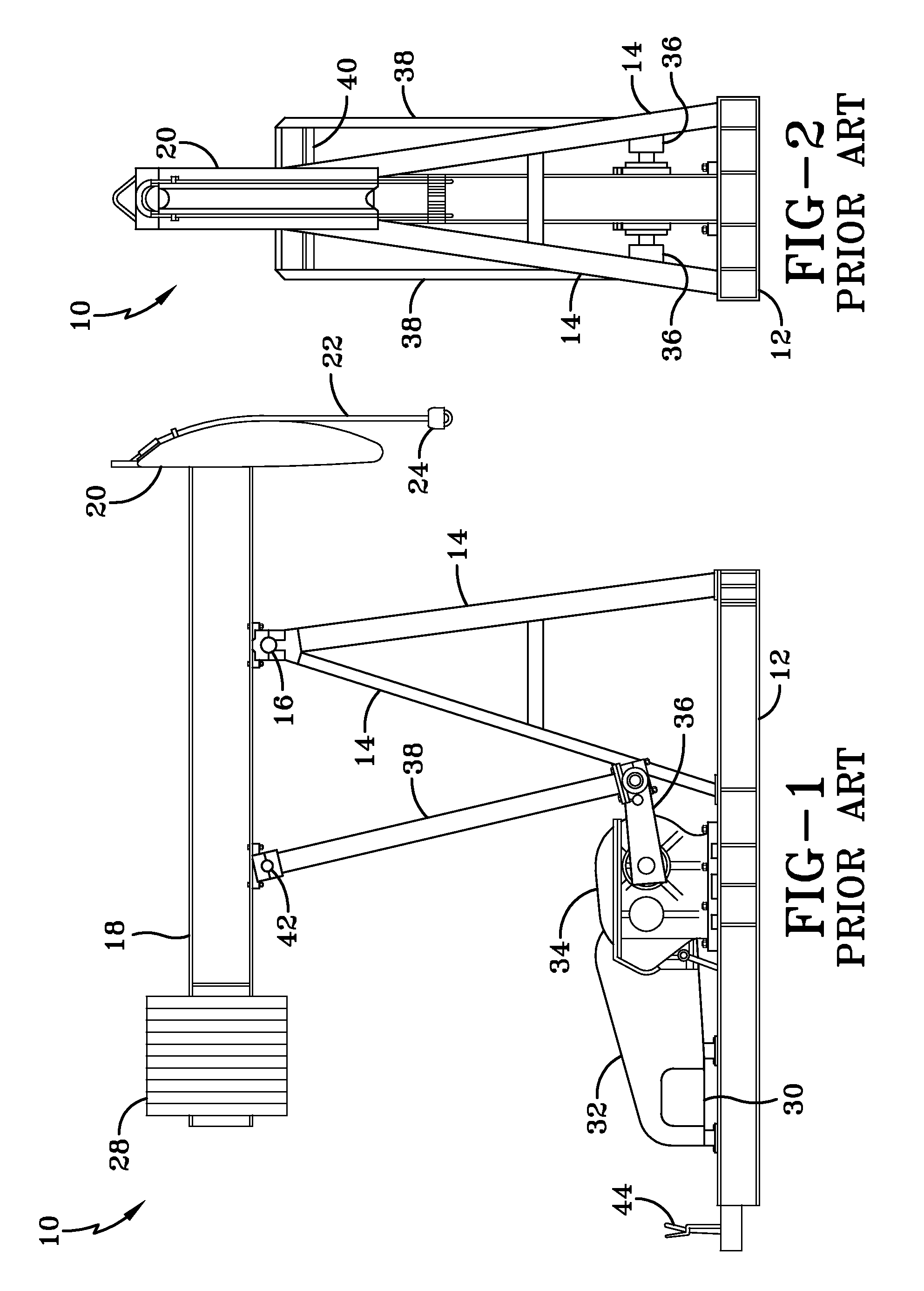
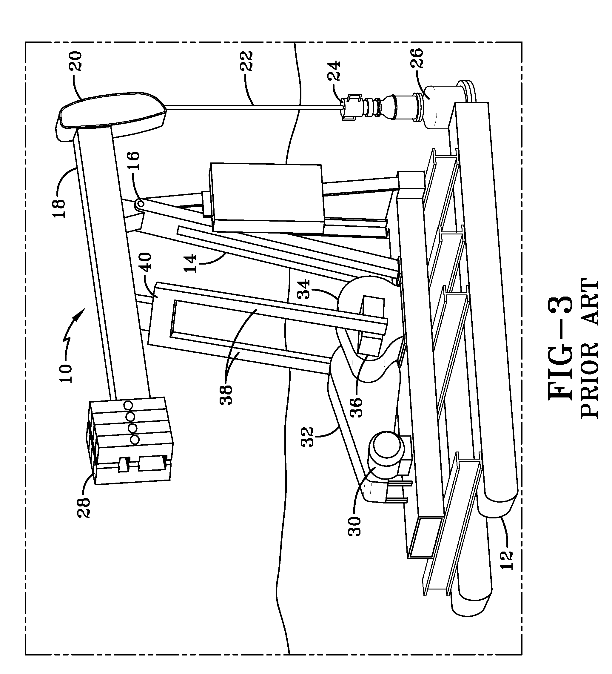
[0065]So that the structure, operation and advantages of the pumping unit of the present invention can best be understood, a typical prior art pumping unit is shown in FIGS. 1-4, and now will be described. With particular attention to FIGS. 1-3, the prior art pumping unit is indicated generally at 10, and includes a base 12 that is placed on a foundation adjacent the bore hole of a well (not shown). A plurality of integrated support posts 14, each of which is known in the art as a Samson post, is mounted on base 12 and extends upwardly to a center bearing 16. A walking beam 18 is mounted on center bearing 16 so that the center bearing is the pivot point for oscillation of the beam. A horse head 20 is attached to a forward end of walking beam 18, and a wireline 22 is attached to and extends between the horse head and a carrier bar 24. Carrier bar 24 in turn is attached to a rod string 26 (FIG. 3), which extends into the well. As described above, wireline 22 follows the curve of horse...


PUM


Abstract

A pumping unit that removes fluid from a well includes a base disposed on a foundation adjacent the well. A group of support posts is mounted on the base and extends upwardly to a center bearing, and is connected to the center bearing. A walking beam is pivotally mounted on the bearing. A Pitman arm is pivotally connected to the walking beam rearwardly of the center bearing, and extends downwardly to a crank assembly. The crank assembly is mounted on the base centrally beneath the Pitman arm, and is pivotally connected to the Pitman arm. A gear reducer is mounted on the side of the crank assembly, and a drive unit is mounted on the base and is connected to the gear reducer. Actuation of the drive unit actuates movement of the gear reducer, crank assembly, Pitman arm, and the walking beam to pump the fluid from the well.

Description

CROSS-REFERENCE TO RELATED APPLICATIONS[0001]This application claims the benefit of U.S. Provisional Patent Application Ser. No. 61 / 078,620, which was filed on Jul. 7, 2008.BACKGROUND OF THE INVENTION[0002]1. Technical Field[0003]The invention relates generally to the art of pumping units for oil and gas wells. More particularly, the invention relates to pumping units for oil and gas wells that have relatively moderate or modest production volume, in which the pumping unit is the above-ground drive mechanism for a reciprocating piston pump that is installed in the borehole of the well. Still more particularly, the pumping unit of the present invention provides an efficient, balanced crank arm design, a planetary gear reduction system mounted on the side of the crank arm design, and other features that improve the performance of the pumping unit, increase the safety of the pumping unit, and decrease the costs associated with the pumping unit.[0004]2. Background Art[0005]In order to m...

Claims


Application Information

Patent Timeline
Patent Type & Authority Applications(United States)
IPC IPC(8): F16H21/22
CPCE21B43/127F04B47/022F04B47/028Y10T74/18182
Inventor MATTISON, DAVID BRUCEPAUMIER, JAMES J.
Owner NEW RIVER EQUIP
Learn More