
Morselizer

a skeletal structure and bone technology, applied in the field of morselizers, can solve the problems of undesirable outcomes, weak regions that may be broken off, and difficult bone cavity formation

Inactive Publication Date: 2010-07-01
SPINEALIGN MEDICAL
View PDF99 Cites 18 Cited by
  • Summary
  • Abstract
  • Description
  • Claims
  • Application Information

AI Technical Summary

Benefits of technology

[0009]Described herein are bone morcelizers for forming cavities in bone, particularly cancellous bone. In general, these devices include an outer cannulated member coupled to a proximal handle. An inner member may be extended and rotate relative to the outer member in a controlled manner, by operating one or more controls on the handle or on a proximal handle attached to the inner rod.

Problems solved by technology

The formation of a bone cavity is often difficult, due to the size constraints, as well as the stresses placed on the devices used to form the cavities in bone.
Such hinges or hinge points often result in weak regions that may be broken off during use.
Breaking of the morcelizer is likely to result in trauma and undesirable outcomes.
Furthermore, the handle and grip regions of currently available devices may be difficult to operate.
In addition, the tip region of the morcelizer may be insufficient, and may lack orientation.

Method used


Image

  • Morselizer
  • Morselizer
  • Morselizer

Examples


Embodiment Construction

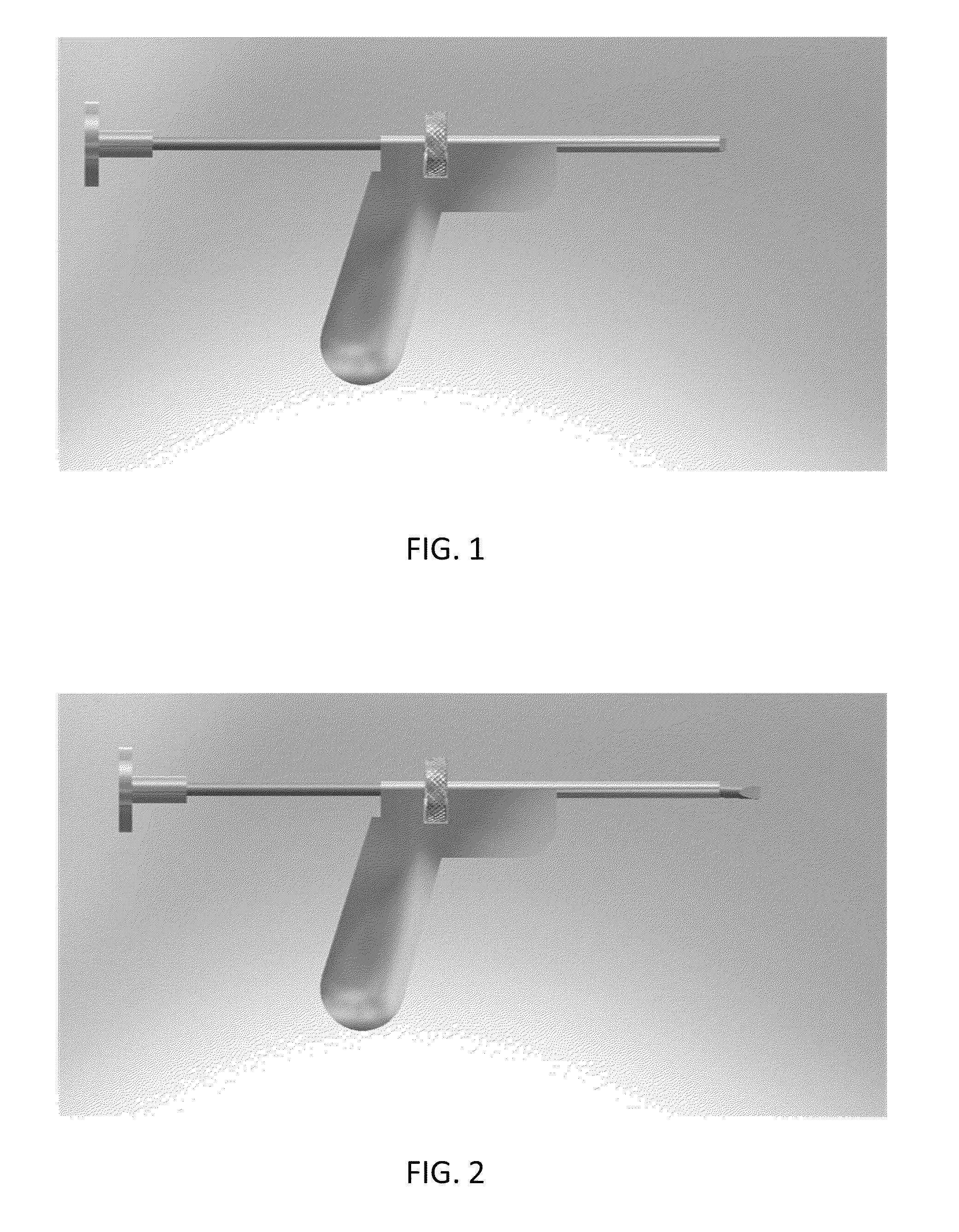
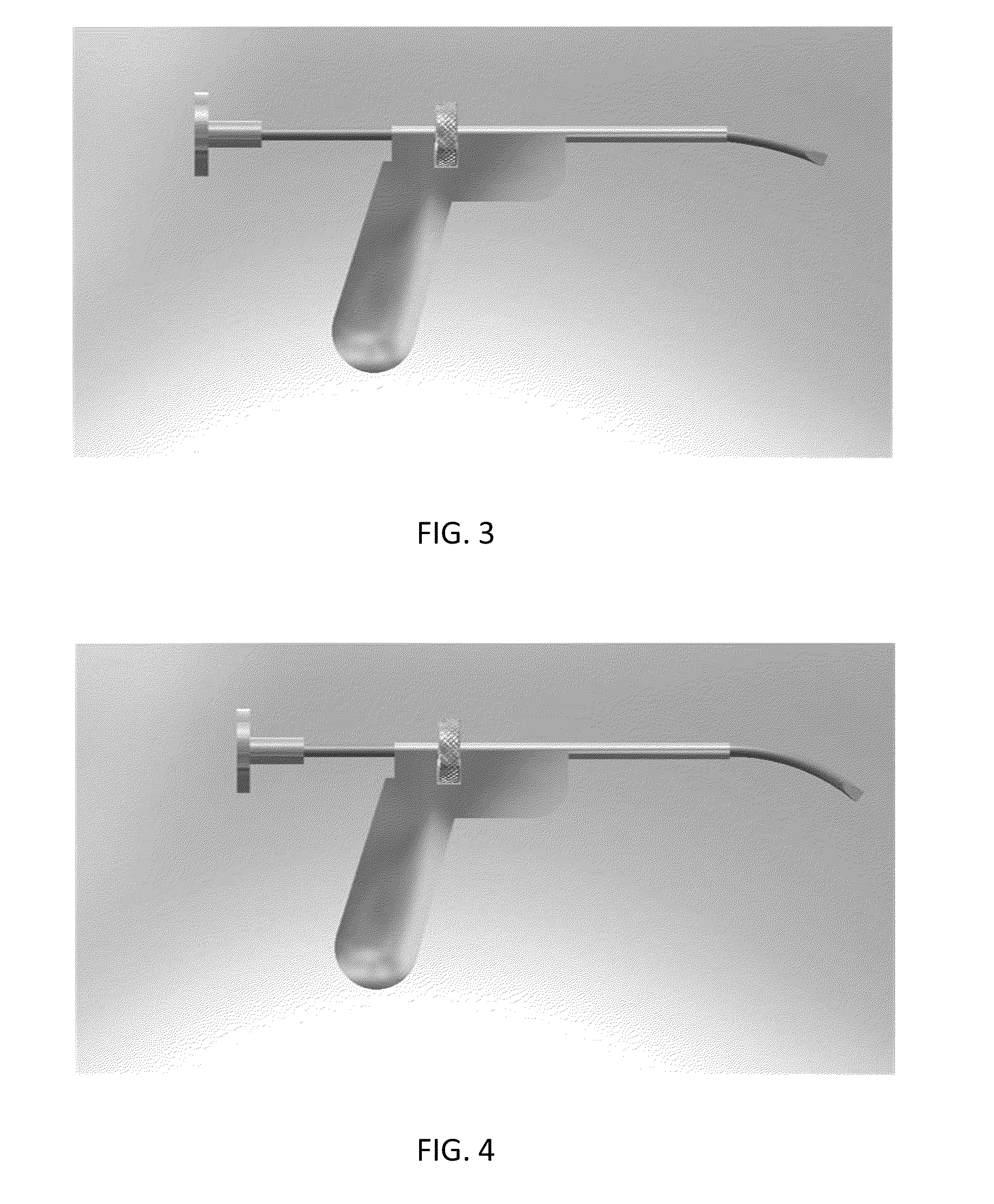
[0029]FIG. 1 illustrates one variation of a morcelizer. In general, this device includes an outer cannulated member that is connected (rigidly) to a handle, an inner member that is movable and lockable with respect to the inner member. At least the distal region of the inner member may be pre-shaped so that it assumes a curved or bent configuration when exiting the device. The device typically also includes one or more locks that may securely lock the inner member in position relative to the outer member. For example, in FIG. 1, the lock is a thumbwheel that can be rotated to lock the inner member in position relative to the outer member.

[0030]The inner member may be configured to extend from the outer member so that it can assume a curved shape. The inner member (rod) can be rotated independently of the outer member and handle, or it can be locked so that moving the handle will move the inner member, allowing formation of a cavity.

[0031]In the example, shown in FIGS. 1-9, the compo...


PUM


Abstract

Described herein are bone morcelizers for forming cavities in bone, particularly cancellous bone. In general, these devices include an outer cannulated member coupled to a proximal handle. An inner member may be extended and rotated relative to the outer member in a controlled manner, by operating one or more controls on the handle. The inner member may assume a curved shape relative to the outer member when it is extended.

Description

CROSS-REFERENCE TO RELATED APPLICATIONS[0001]This application claims the benefit of priority to U.S. Provisional Patent Application Ser. No. 61 / 081,308, titled “MORSELIZER”, filed on Jul. 16, 2008 and U.S. Provisional Patent Application Ser. No. 61 / 121,309, titled “MORSELIZER”, filed on Dec. 10, 2008, herein incorporated by reference in their entirety.[0002]This provisional patent application may be related to U.S. patent application Ser. No. 12 / 025,537, titled “METHODS AND DEVICES FOR STABILIZING BONE COMPATIBLE FOR USE WITH BONE SCREWS”, filed on Feb. 4, 2008. This application may also be related to U.S. patent application Ser. No. 11 / 468,759, filed on Aug. 30, 2006, which claims the benefit of U.S. Provisional Patent Application Ser. No. 60 / 713,259, filed on Aug. 31, 2005, and to U.S. Provisional Patent Application Ser. No. 60 / 916,731, filed on May 8, 2007. All of these applications are incorporated herein by reference in their entirety.INCORPORATION BY REFERENCE[0003]All publica...

Claims


Application Information

Patent Timeline
Patent Type & Authority Applications(United States)
IPC IPC(8): A61B17/00
CPCA61B17/1617A61B17/8858A61B2017/00867A61B2018/00601A61B18/1482
Inventor KNOPP, PETER G.CHIRICO, PAUL E.CHAN, BENNY M.SOUZA, ALISON M.
Owner SPINEALIGN MEDICAL
Learn More