
Temperature control system for fuel cell

a technology of temperature control system and fuel cell, which is applied in the direction of fuel cell technology, transportation hydrogen technology, electric generators, etc., can solve the problems of system enlargement and end cells radiating heat, and achieve the effect of suppressing cell voltage fluctuation

Inactive Publication Date: 2010-07-01
TOYOTA JIDOSHA KK
View PDF4 Cites 9 Cited by
  • Summary
  • Abstract
  • Description
  • Claims
  • Application Information

AI Technical Summary

Benefits of technology

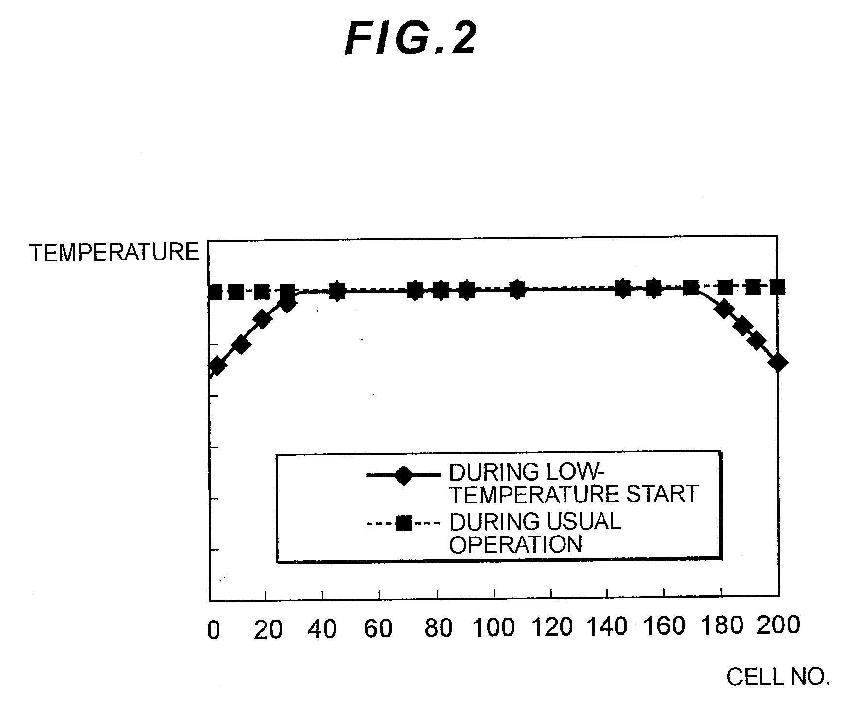
[0009]Here, the “low temperature” is, for example, a temperature lower than ordinary temperature, a temperature around zero degree, or a temperature below the freezing point. The “flow rate larger than that for the usual operation” includes an absolute flow rate, a flow speed and a pressure. According to such a constitution, the flow rate of the heat transfer medium (cooling water or the like) for low-temperature start is set to a flow rate larger than that of the heat transfer medium for normal start, so that a temperature fluctuation among cells can be suppressed even in the case of warm-up for the low-temperature start, and as a result, the cell voltage fluctuation can be suppressed.
[0012]As described above, according to the present invention, a cell voltage fluctuation can be suppressed even in the case of starting under a low-temperature environment.

Problems solved by technology

However, there is a problem that in the case of an operation (start or the like) under a low-temperature environment, end cells radiate heat to generate a larger temperature gradient in a stack.
There is also a problem that in a case where the above-mentioned insulating plates are arranged, a system enlarges.

Method used


Image

  • Temperature control system for fuel cell
  • Temperature control system for fuel cell
  • Temperature control system for fuel cell

Examples


Embodiment Construction

[0022]An embodiment according to the present invention will hereinafter be described with reference to the drawings.

A. Present Embodiment

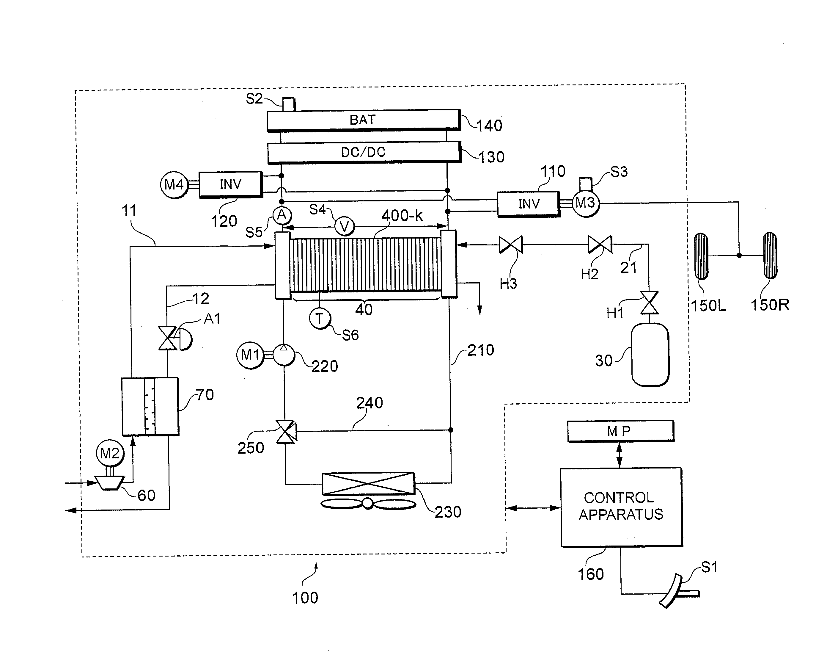
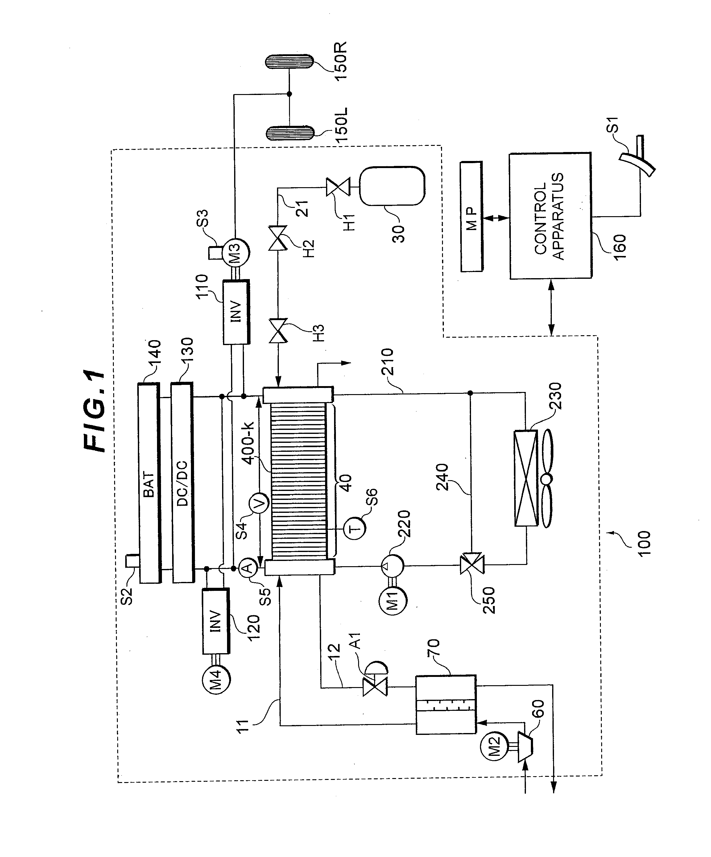
[0023]FIG. 1 is a diagram showing the main part constitution of a fuel cell system 100 according to the present embodiment. In the present embodiment, a fuel cell system to be mounted on a vehicle such as a fuel cell car (FCHV), an electric car or a hybrid car is assumed, but the present invention is applicable not only to the vehicle but also to any type of mobile body (e.g., a ship, an airplane, a robot or the like) and a stational power source.

[0024]A fuel cell 40 is means for generating power from a supplied reaction gas (a fuel gas and an oxidizing gas), and has a stack structure in which a plurality of unitary cells 400-k (1≦k≦n) each including a membrane / electrode assembly (MEA) and the like are laminated in series. Specifically, various types of fuel cells such as a solid polymer type, a phosphoric acid type and a dissolved carbonate type m...


PUM


Abstract

Provided is a temperature control system which can suppress a cell voltage fluctuation even in the case of starting under a low-temperature environment. The temperature control system for a fuel cell according to the present invention circulates a heat transfer medium through the fuel cell to control the temperature of the fuel cell. The system is characterized by including circulation control means for circulating, through the fuel cell, the heat transfer medium having a flow rate larger than that for a normal operation during a low-temperature operation. According to such a constitution, the flow rate of the heat transfer medium (cooling water or the like) for low-temperature start is set to a flow rate larger than that of the heat transfer medium for normal start, so that a temperature fluctuation among cells can be suppressed even in the case of warm-up for the low-temperature start, and as a result, the cell voltage fluctuation can be suppressed.

Description

TECHNICAL FIELD[0001]The present invention relates to a temperature control system for a fuel cell.BACKGROUND ART[0002]A fuel cell system is known in which power is generated using the electrochemical reaction between a fuel gas including hydrogen and an oxidizing gas including oxygen. Such a fuel cell is highly efficient clean power generation means, and is hence largely expected as a driving power source for a two-wheeled vehicle, a car and the like.[0003]However, the fuel cell has poor starting properties as compared with another power source, and a cell voltage fluctuation is generated between the ends of the fuel cell and the center thereof especially in a case where the system is started under a low-temperature environment. In general, end plates are provided on both the ends of the fuel cell in which a plurality of cells are laminated (see FIG. 9). When the system is started at a low temperature, a fuel cell 1 is warmed up by effectively using self heat generation accompanyin...

Claims


Application Information

Patent Timeline
IPC IPC(8): H01M8/04
CPCH01M8/04029H01M8/04268H01M8/0432H01M8/04768H01M2008/1095H01M2250/20Y02T90/32Y02E60/50Y02T90/40H01M8/04
Inventor MANABE, KOTA
Owner TOYOTA JIDOSHA KK
Learn More