
Optical transceiver IC

a technology of optical transceivers and integrated circuits, applied in electromagnetic transceivers, pulse manipulation, pulse techniques, etc., can solve problems such as problems such as typical analog approaches, input is not a continuous stream,

Active Publication Date: 2010-07-01
INTEL CORP
View PDF11 Cites 10 Cited by
  • Summary
  • Abstract
  • Description
  • Claims
  • Application Information

AI Technical Summary

Problems solved by technology

That is, the input is not a continuous stream at all time anymore, and problems are raised for the typical analog approach.

Method used


Image

  • Optical transceiver IC
  • Optical transceiver IC
  • Optical transceiver IC

Examples


Embodiment Construction

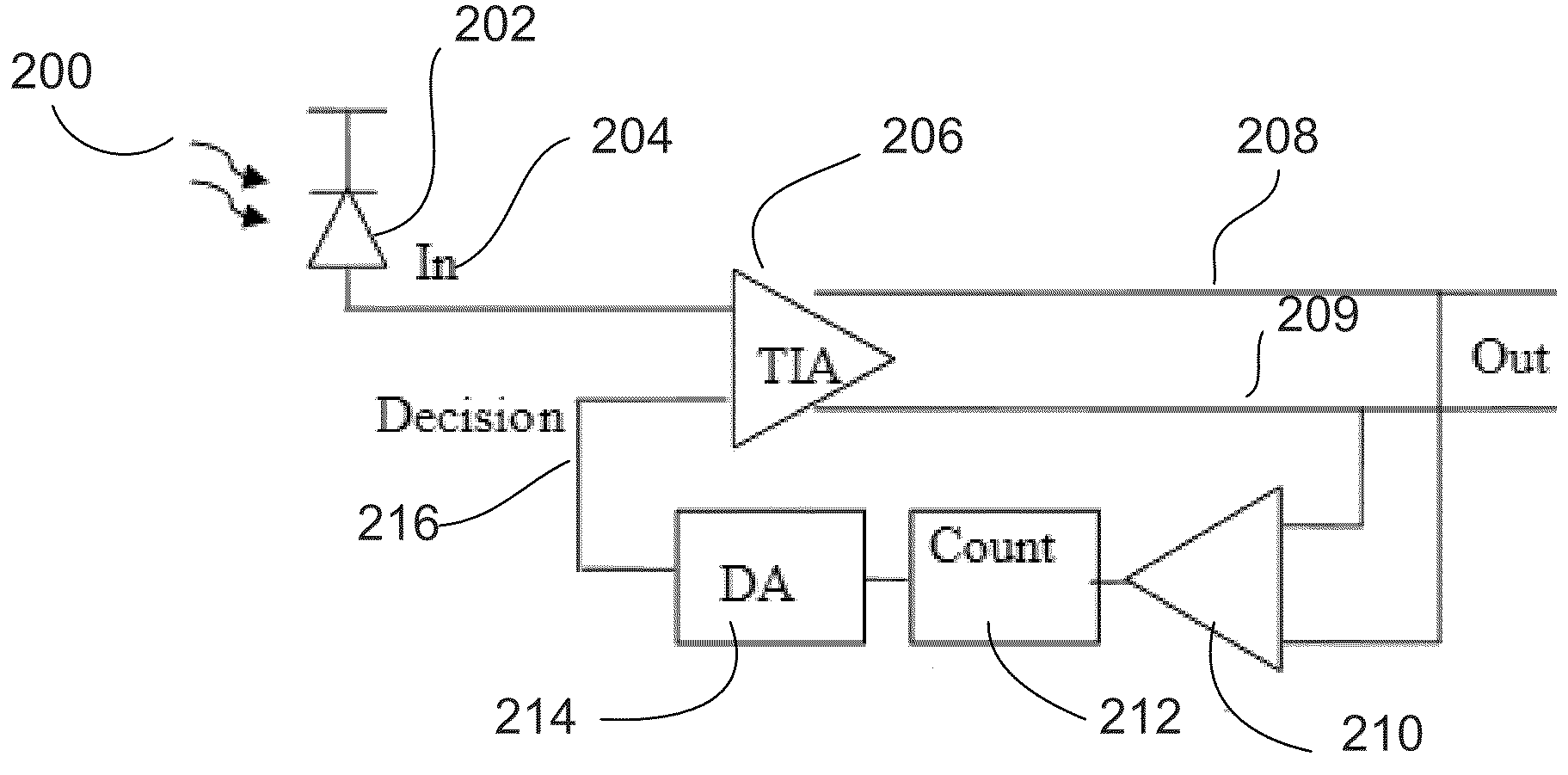
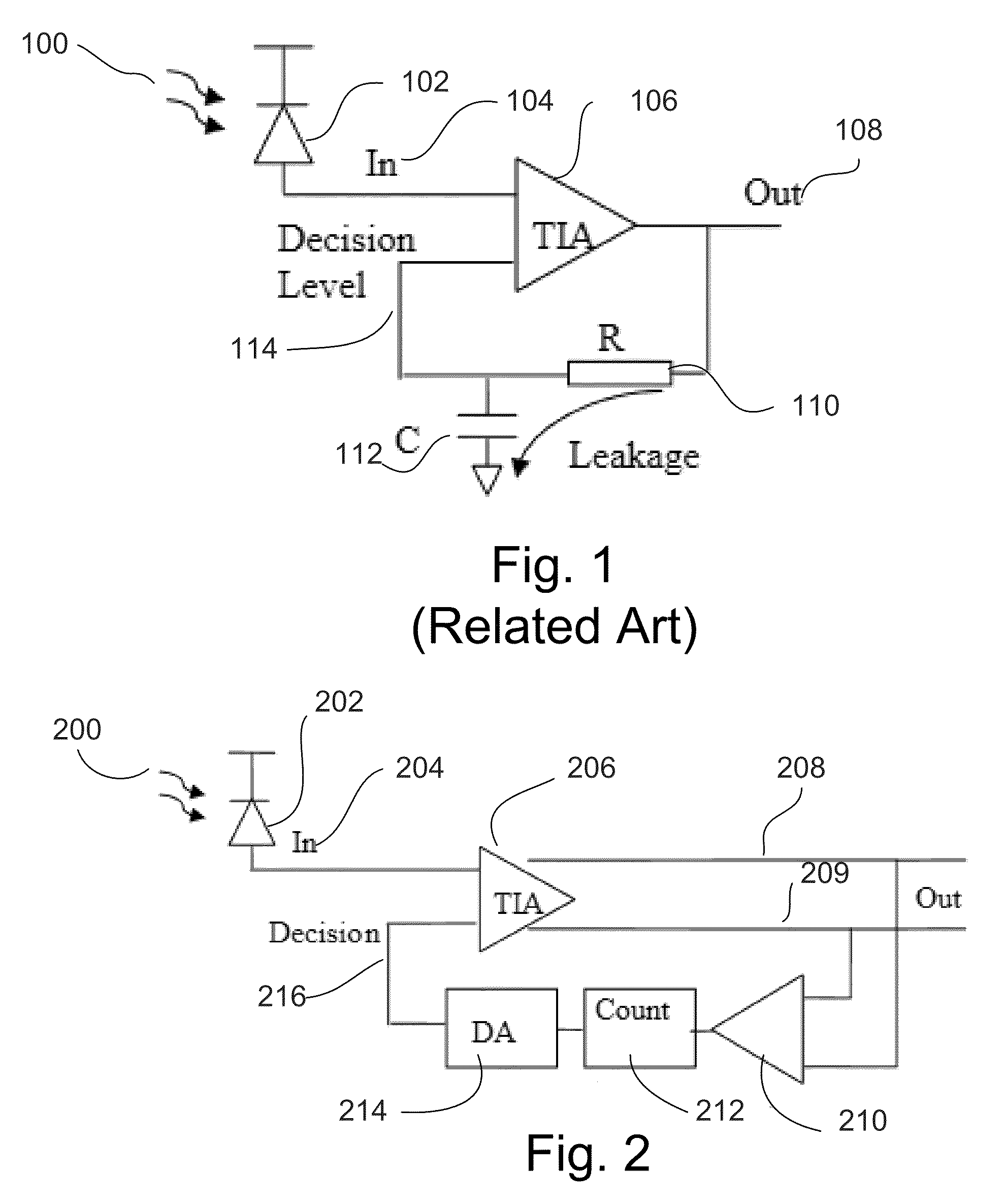
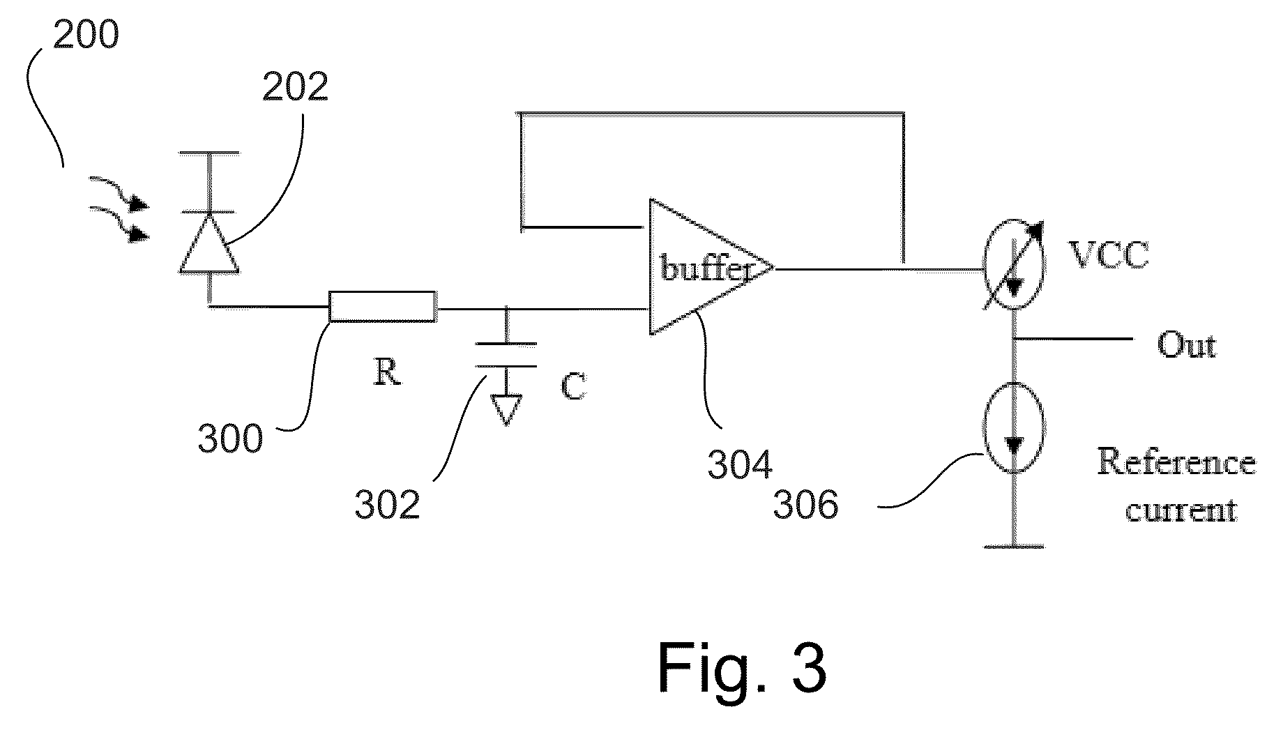
[0011]Described is power management arrangement for low power optical transceiver such as those that may be integrated into a personal computer or server that periodically puts itself into a power conservation or sleep mode which assures the transceiver is available upon wake-up.

[0012]Reference throughout this specification to “one embodiment” or “an embodiment” means that a particular feature, structure, or characteristic described in connection with the embodiment is included in at least one embodiment of the present invention. Thus, the appearances of the phrases “in one embodiment” or “in an embodiment” in various places throughout this specification are not necessarily all referring to the same embodiment. Furthermore, the particular features, structures, or characteristics may be combined in any suitable manner in one or more embodiments.

[0013]A photodiode as referred to herein relates to a device that provides an output current in response to light energy collected on a surfa...


PUM


Abstract

A power management arrangement for low power optical transceiver such as those that may be integrated into a personal computer or server may periodically put itself into a power conservation or sleep mode which assures the transceiver is available upon wake-up.

Description

FIELD OF THE INVENTION[0001]Embodiments of the present invention are directed to low power optical transceiver integrated circuits and, more particularly, to power management for optical transceivers.BACKGROUND INFORMATION[0002]Optical communication networks have been implemented to enable increased data rates in links providing point to point communication. For example, optical communication links may be implemented in Synchronous Optical Network / Synchronous Digital Hierarchy (SONET / SDH) and 10 Gigabit Ethernet systems. At a receiving end of such an optical communication link, a photodiode may generate a current in response an optical signal received from an optical transmission medium (e.g., fiber optical cabling). A transimpedance amplifier (TIA) typically converts the current generated by the photodiode into a voltage signal that is then processed. For example, the voltage signal may be processed by clock and data recovery circuitry to recover data transmitted in the optical sig...

Claims


Application Information

Patent Timeline
Patent Type & Authority Applications(United States)
IPC IPC(8): H04B10/06H04B10/00
CPCH03K5/086H04B10/69H04B10/00H04B10/40
Inventor WU, HUI-CHINGAO, MIAOBINCHENG, HENGJU
Owner INTEL CORP
Learn More