Image stabilizer for optical instrument
a technology of image stabilizer and optical instrument, which is applied in the field of image stabilizer, can solve the problems of affecting the smooth shift of optical elements, affecting the followability of the holder to the actuator, and the size of the image stabilizer type, so as to reduce the number of parts, and improve the accuracy of the image stabilizer
- Summary
- Abstract
- Description
- Claims
- Application Information
AI Technical Summary
Benefits of technology
Problems solved by technology
Method used
Image
Examples
first embodiment
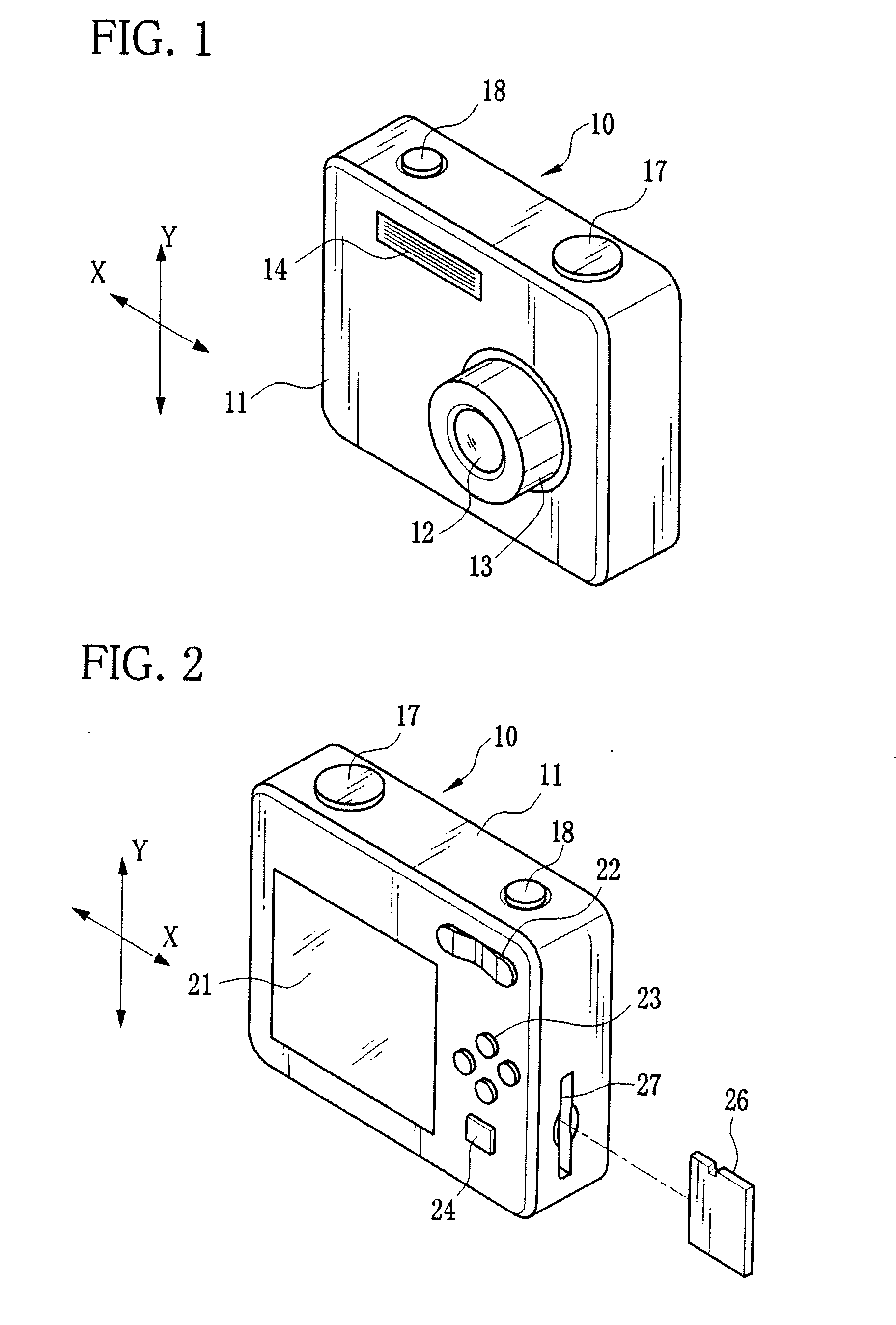
[0038]As shown in FIG. 1, a digital still camera 10 has a lens barrel 13 for containing an optical system 12, a flashlight emitter 14 for applying flashlight to an object and the like in a front face of a camera body 11.
[0039]On a top face of the camera body 11, there are provided operating members including an operation dial 17 and a shutter button 18. The operation dial 17 is used for turning the power on and off, and switching an operation mode (among a photographing mode, a playback mode and the like). The shutter button 18 is a two-step push switch, and used for taking an image. Upon turning on a first-step switch SW1 by a half press of the shutter button 18, the digital still camera 10 makes preparation for image taking (exposure setting and focusing). After that, when a second-step switch SW2 is turned on by a full press of the shutter button 18, the digital still camera 10 captures a still image and stores image data on a memory card 26.
[0040]As shown in FIG. 2, a liquid cry...
second embodiment
[0082]In a second embodiment, the first sheet metal member and the second sheet metal member are integrally formed into one body by bending a single sheet of metal, for the purpose of further improving orthogonality between the horizontal leaf springs and the vertical leaf springs and facilitating assembly. The same reference numbers as the first embodiment indicate substantially the same elements or parts, and description thereof will be omitted.
[0083]In an integrated sheet metal member 90 made of a metal leaf spring material, as shown in FIG. 9, a coupling section 91 corresponding to the intermediate member 66 couples the first sheet metal member 68 and the second sheet metal member 69 according to the first embodiment. The integrated sheet metal member 90 has a pair of horizontal leaf springs 68b extending in the X-axis direction and a pair of vertical leaf springs 69b extending in the Y-axis direction.
[0084]The integrated sheet metal member 90 is used instead of the intermediate...
third embodiment
[0086]In the foregoing embodiments, the CCD is attached to the CCD holder by use of the CCD retaining plate. However, the first sheet metal member 68 according to the first embodiment or the integrated sheet metal member 90 according to the second embodiment may have the function of the CCD retaining plate, to obviate the CCD retaining plate. The following third embodiment describes a case where the first sheet metal member 68 has the function of the CCD retaining plate. The same reference numbers as the first and second embodiments indicate substantially the same elements or parts, and description thereof will be omitted.
[0087]A first sheet metal member 100, as shown in FIG. 11, integrally has an arm 101 that extends on a rear side from an upper end of the CCD holder attachment section 68c in a downward direction. The arm 101 is bent behind the CCD holder 65, and fixed to the CCD holder 65 at an end with a screw 102. In the middle of the arm 101, a retainer 103 is projected so as t...
PUM
 Abstract
Description
Claims
Application Information
 - R&D
- Intellectual Property
- Life Sciences
- Materials
- Tech Scout
- Unparalleled Data Quality
- Higher Quality Content
- 60% Fewer Hallucinations
Browse by: Latest US Patents, China's latest patents, Technical Efficacy Thesaurus, Application Domain, Technology Topic, Popular Technical Reports.
© 2025 PatSnap. All rights reserved.Legal|Privacy policy|Modern Slavery Act Transparency Statement|Sitemap|About US| Contact US: help@patsnap.com


