
Low voltage bandgap reference circuit

Inactive Publication Date: 2010-07-01
NOVATEK MICROELECTRONICS CORP
View PDF4 Cites 16 Cited by
  • Summary
  • Abstract
  • Description
  • Claims
  • Application Information

AI Technical Summary

Benefits of technology

[0008]The invention is directed to a low voltage bandgap reference circuit capable of generating a low reference voltage. According to an embodiment of the invention, the low voltage bandgap reference circuit can generate the reference voltage by using an additional circuit of lower complexity.

Problems solved by technology

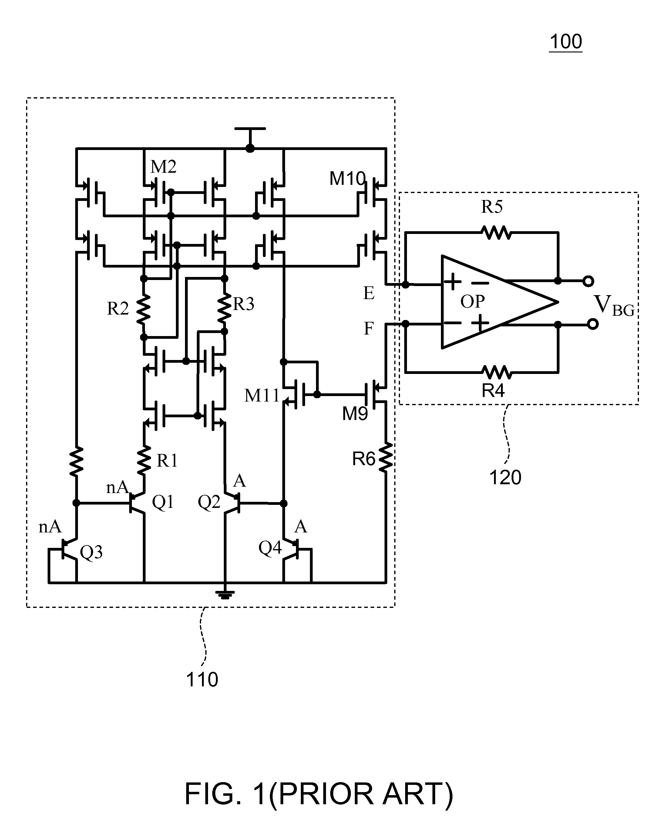
The additional circuit is normally composed of complicated analog elements, thereby increasing the circuit area of the whole system and thus the circuit complexity and production cost.

Method used


Image

  • Low voltage bandgap reference circuit
  • Low voltage bandgap reference circuit
  • Low voltage bandgap reference circuit

Examples


embodiment one

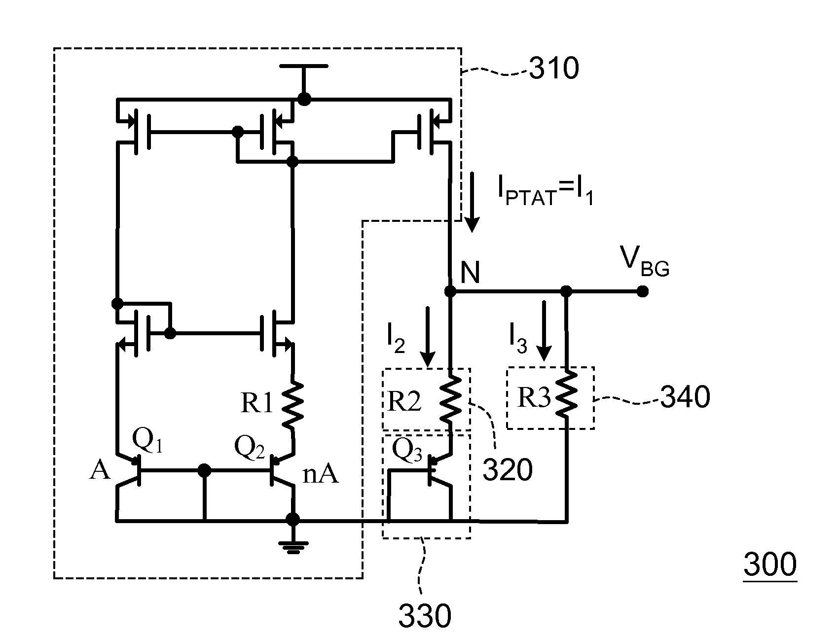
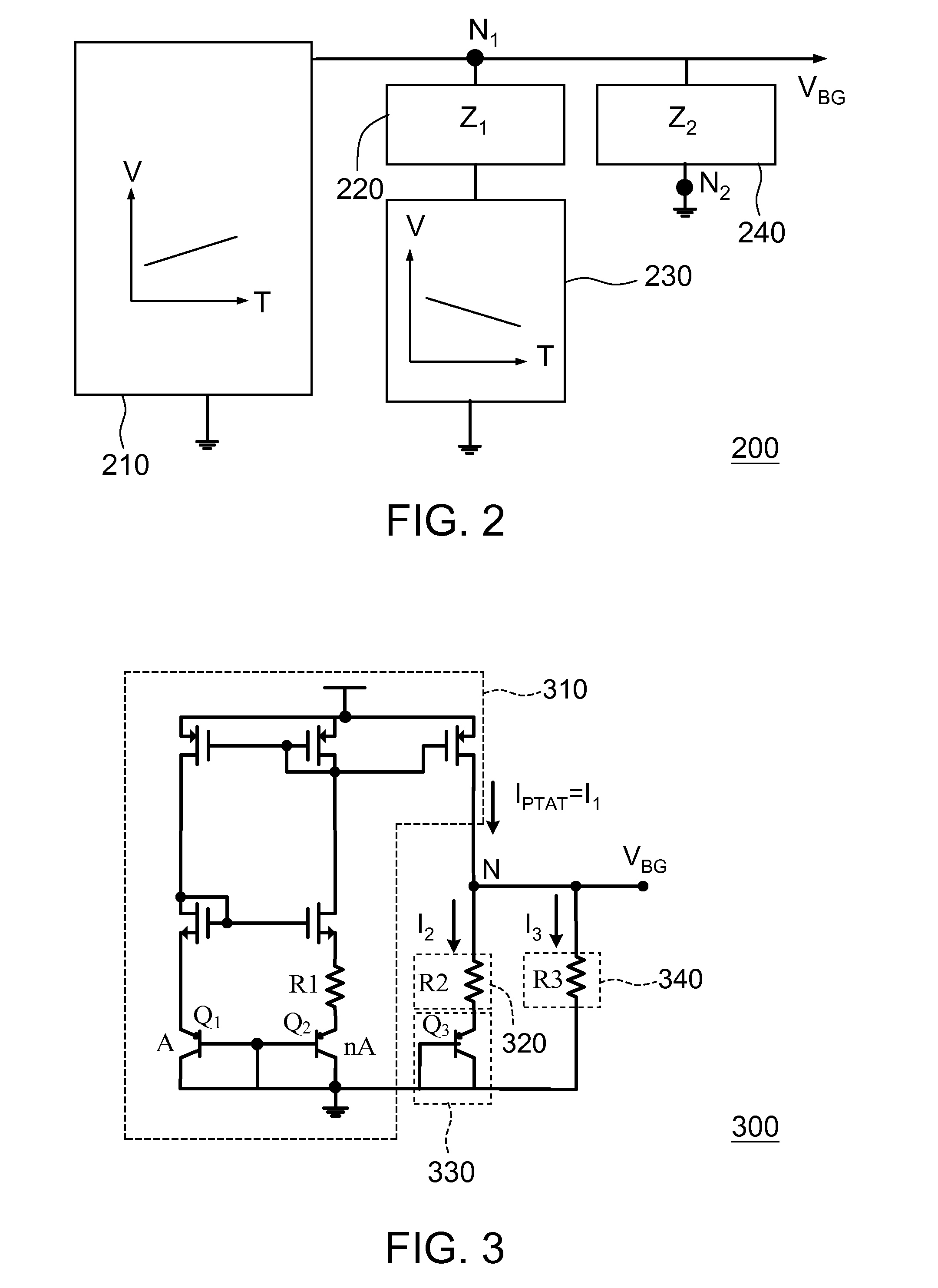
[0022]Referring to FIG. 2, a block diagram of a bandgap reference circuit is shown according to a first embodiment of the invention. In FIG. 2, a bandgap reference circuit 200 is used for generating an output reference voltage VBG. The bandgap reference circuit 200 includes a first reference signal generator 210, a first impedance 220, a second reference signal generator 230 and a second impedance 240. The bandgap reference voltage VBG is substantially independent of temperature and is detetermined by impedances Z1 and Z2 of the first impedance 220 and the second impedance 240. As shown below, the output reference voltage VBG can be used to obtain a bandgap reference voltage smaller than the standard value 1.25V.

[0023]The first reference signal generator 210 has an output terminal coupled to a first node N1 and generates a first reference signal proportional to absolute temperature (PTAT) from the output terminal, such as a current IPTAT having a positive temperature coefficient. Th...

embodiment two

[0038]Referring to FIG. 8, a block diagram of a bandgap reference circuit according to a second embodiment of the invention is shown. The difference between the bandgap reference circuit of FIG. 8 and the bandgap reference circuit 200 of FIG. 2 lies in that the first reference signal generator 810 of the bandgap reference circuit 800 is a circuit having the characteristic of negative temperature coefficient, and the second reference circuit generator 830 is a circuit having the characteristic of positive temperature coefficient.

[0039]The first reference signal generator 810 generates a first reference signal complementary to absolute temperature, such as a current ICTAT having a negative temperature coefficient. FIGS. 9, 10 and 11 show examples of the circuits having the characteristic of negative temperature coefficient, which can be employed in implementing bandgap reference circuits according to the second embodiment of the invention.

[0040]The second reference signal generator 83...


PUM


Abstract

A bandgap reference circuit provided for generating an output reference substantially independent of temperature and power includes a first reference signal generator, a first impedance, a second reference signal generator and a second impedance. The first reference signal generator can generate a first reference signal proportional to absolute temperature. The second reference signal generator generates a second reference signal complementary to absolute temperature according to the first reference signal. The second impedance, the serially-coupled first impedance and second reference signal generator, and the first reference signal generator are coupled in parallel between two nodes. The bandgap reference circuit outputs the output reference voltage through the two nodes. According to an embodiment of the invention, the bandgap reference circuit can be implemented by an additional circuit of lower complexity to obtain a lower reference voltage.

Description

[0001]This application claims the benefit of Taiwan application Serial No. 97151102, filed Dec. 26, 2008, the subject matter of which is incorporated herein by reference.BACKGROUND OF THE INVENTION[0002]1. Field of the Invention[0003]The invention relates in general to a bandgap reference circuit, and more particularly to a low voltage bandgap reference circuit.[0004]2. Description of the Related Art[0005]The bandgap reference circuit is widely applied in an integrated circuit, typically for supplying a reference voltage of about 1.25V. The reference voltage is more accurate than a voltage supplied by an external power source and less influenced by temperature and power supply variation. The bandgap reference circuit uses a circuit operating proportional to the absolute temperature to compensate a negative temperature coefficient between a base and an emitter of a bipolar transistor in order to obtain a reference voltage substantially independent of temperature variation.[0006]In or...

Claims


Application Information

Patent Timeline
IPC IPC(8): G05F3/16
CPCG05F3/30
Inventor YANG, CHIH-HSUN
Owner NOVATEK MICROELECTRONICS CORP
Learn More