
Applications of hydrogen gas getters in mass spectrometry

a hydrogen gas and mass spectrometry technology, applied in the field of mass spectrometry, can solve the problems of white deposits on the tube, waste of gas getters, and the reaction of getters

Inactive Publication Date: 2010-07-01
UNIVERSITY OF NORTH TEXAS
View PDF6 Cites 13 Cited by
  • Summary
  • Abstract
  • Description
  • Claims
  • Application Information

AI Technical Summary

Benefits of technology

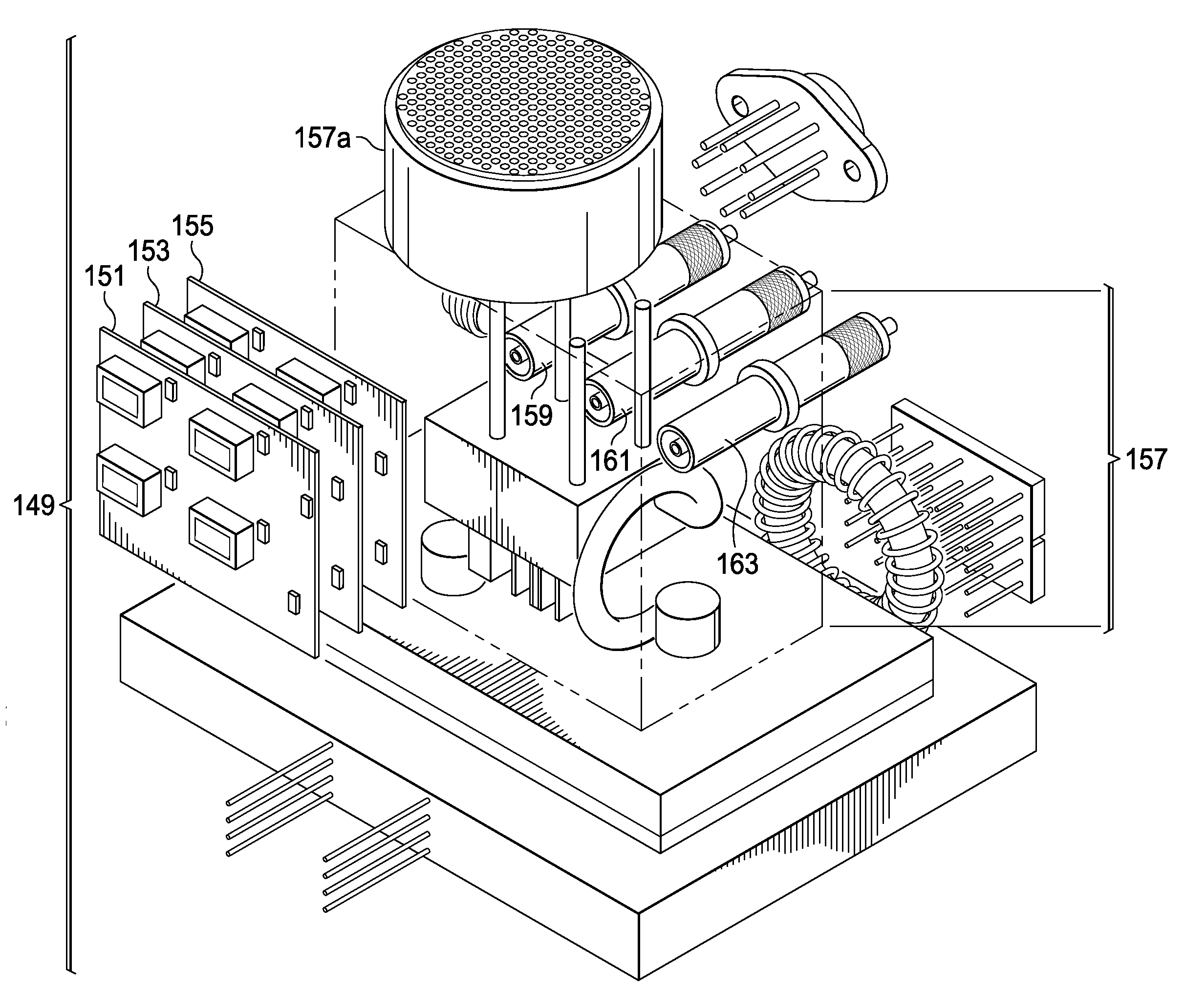
[0011]In one embodiment the present invention is an electrically controlled getter device that comprises a substrate comprising a metal alloy, with the substrate is in fluid communication with one or more pumps and the flow of a fluid in contact with the metal alloy is controlled by one or more microvalves positioned between a source of a fluid and the metal alloy. Gaseous materials are adsorbed and selectively released on application of an electrical charge to the metal alloy. The device of the present invention can be typically incorporated within a mass spectrometer, a small SEM, a vacuum pump, or similar portable devices. In one aspect, a mass spectrometer incorporating the present invention is a quadrupole ion trap mass spectrometer comprised of either hyperbolic or cylindrical ring electrodes. In a further aspect, the one or more pumps of the present invention are coated with a material that comprises a metal alloy, which may be selected from zirconium, vanadium, iron, cobalt, aluminum, rare earth metals, lanthanum, cerium, praseodymium, neodymium, or combinations thereof. In another aspect, the coating material of the present invention reacts irreversibly with oxygen, carbon-dioxide, water vapor, and nitrogen, and reacts reversibly and adsorbs hydrogen and inert gases.
[0012]In another embodiment the present invention describes a method for analysis of a sample, comprising the steps of: transforming one or more molecules of the sample to one or more ionized particles; sorting the one or more ionized particles by the application of an electric field, a magnetic field or both; trapping the one or more ionized particles in an ion trap, wherein the ion trap comprises a substrate coated with a metal alloy, wherein the substrate is in fluid communication with one or more pumps and a flow of a fluid in contact with the metal alloy is controlled by one or more microvalves positioned between a source of a fluid and the metal alloy, wherein the metal alloy adsorbs gaseous materials upon the application of an electrical charge to the metal alloy and selectively releases certain gases; ejecting the one or more ionized particles from the ion trap; and detecting a total ionic current from the one or more ionized particle.
[0013]In one aspect, the present invention describes a method for analysis of a sample that comprises one or more organic molecules, inorganic molecules, biomolecules, proteins, peptides, pollutants, environmental contaminants, liquid explosives, bioterrorist agents, or combinations thereof. In a further aspect the sample is transformed to one or more ionic particles by a chemical or thermal ionization method. In another aspect, the ion trap comprises a quadrupole comprising of hyperbolic or cylindrical ring electrodes and is pressurized with a gas. In yet another aspect the ion trap comprises a gaseous material to buffer the ions.
[0014]In another aspect, the one or more pumps are coated with a material comprising a metal alloy selected from zirconium, vanadium, iron, cobalt, aluminum, rare earth metals, lanthanum, cerium, praseodymium, neodymium, or combinations thereof. In yet another aspect the coating material reacts irreversibly with oxygen, carbon-dioxide, water vapor, and nitrogen and reversibly with hydrogen and inert gases. In a further aspect of the present invention, the material adsorbs hydrogen gas that is then used to pressurize the ion trap and to buffer the ions.

Problems solved by technology

If the tube is broken, the getter reacts with incoming air leaving a white deposit on the tube, and becomes useless; for this reason getters are not used in systems which are intended to be opened.

Method used


Image

  • Applications of hydrogen gas getters in mass spectrometry
  • Applications of hydrogen gas getters in mass spectrometry
  • Applications of hydrogen gas getters in mass spectrometry

Examples


Embodiment Construction

[0026]While the making and using of various embodiments of the present invention are discussed in detail below, it should be appreciated that the present invention provides many applicable inventive concepts that can be embodied in a wide variety of specific contexts. The specific embodiments discussed herein are merely illustrative of specific ways to make and use the invention and do not delimit the scope of the invention.

[0027]To facilitate the understanding of this invention, a number of terms are defined below. Terms defined herein have meanings as commonly understood by a person of ordinary skill in the areas relevant to the present invention. Terms such as “a”, “an” and “the” are not intended to refer to only a singular entity, but include the general class of which a specific example may be used for illustration. The terminology herein is used to describe specific embodiments of the invention, but their usage does not delimit the invention, except as outlined in the claims.

[...


PUM


Abstract

The present invention is an electrically controlled gettered pump assembly to entrain and fully release hydrogen gas to regulate the pressure and buffer the ions in an ion trap mass spectrometer and other portable analytical instruments. In addition to the gettered pump assembly, the present invention also incorporates a microvalve between the different chambers to release and control the hydrogen content. Hydrogen gas regulates the pressure in mass spectrometers and also acts as a buffering gas to prevent the ions from escaping the trap.

Description

CROSS-REFERENCE TO RELATED APPLICATIONS[0001]This application claims benefit of U.S. Provisional applications Ser. No. 61 / 141,546 filed on Dec. 30, 2008, which are incorporated herein by reference in their entirety.TECHNICAL FIELD OF THE INVENTION[0002]The present invention relates in general to the field of mass spectrometry, and more particularly, to using getter material saturated with hydrogen gas to regulate the pressure needed to run mass spectrometers, to buffer and thermalize the ions, and to prevent their escape from the ion trap.STATEMENT OF FEDERALLY FUNDED RESEARCH[0003]None.INCORPORATION-BY-REFERENCE OF MATERIALS FILED ON COMPACT DISC[0004]None.BACKGROUND OF THE INVENTION[0005]Without limiting the scope of the invention, its background is described in connection with mass spectrometry particularly to the use hydrogen gas entrained in getters to regulate the pressure in mass spectrometers and as a buffering gas to prevent the ions from escaping the trap.[0006]Getters typ...

Claims


Application Information

Patent Timeline
Patent Type & Authority Applications(United States)
IPC IPC(8): H01J49/26H01K1/54
CPCH01J41/20H01J49/24
Inventor VERBECK, IV, GUIDO FRIDOLIN
Owner UNIVERSITY OF NORTH TEXAS
Learn More