
Spinal implant apparatus, method and system

a technology of spinal implants and apparatuses, applied in the field of spinal implant apparatuses, methods and systems for the treatment and management of spinal defects, can solve the problems of spondylosis, tumors or even trauma, and the preservation of natural spinal motion and dynamics, and achieve the effect of facilitating the implantation of the apparatus in the spin

Inactive Publication Date: 2010-06-24
PANNU YASHDIP S
View PDF40 Cites 9 Cited by
  • Summary
  • Abstract
  • Description
  • Claims
  • Application Information

AI Technical Summary

Benefits of technology

The system facilitates safe and efficient insertion of spinal inserts, reducing the risk of migration and pseudoarthrosis, promoting bony fusion and maintaining spinal dynamics, thereby addressing the challenges of spinal defect management and sagittal balance.

Problems solved by technology

The treatment and management of spinal defects remains one of the most challenging aspects of medicine.
They may result from spondylosis, tumor or even trauma.
Preserving natural spinal motion and dynamics remains a considerable challenge.
Therefore, preserving spinal anatomy and stability are even more difficult in any surgical procedure in which a portion or complete section of disc space, vertebrae or several vertebrae is removed.
Restoring natural anatomical length and shape of any bone with spondylosis is problematic.
Restoring spinal anatomy and stability and promoting spinal dynamics or bone fusion are even more difficult in any surgical procedure in which a portion or complete section of a vertebrae one or portion or complete section of a vertebral body or disc space.
The limiting factor often times is the posterior height of the disc space and wedging an insert through this part of the disc space may create longitudinal grooves within the vertebral bodies to allow for migration of the spinal insert back towards the neurologic tissue with subsequent neurologic injury or cause the surgeon to undersize the implant since he or she is gauging the posterior height of the disc space and not allowing the implant to directly interface with the cortical bony surface thereby causing a pseudoarthorosis or bony non union.

Method used


Image

  • Spinal implant apparatus, method and system
  • Spinal implant apparatus, method and system
  • Spinal implant apparatus, method and system

Examples


Embodiment Construction

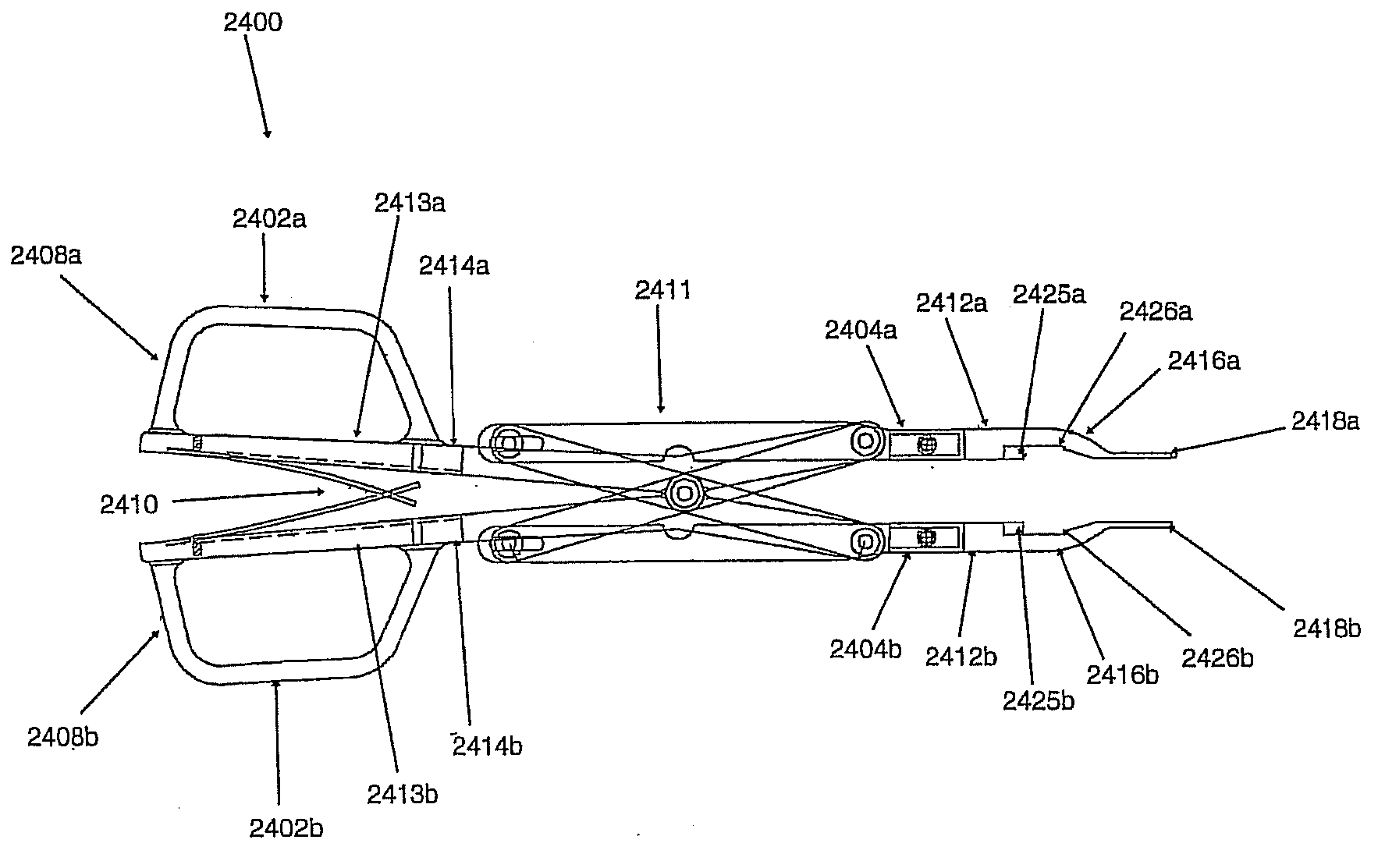
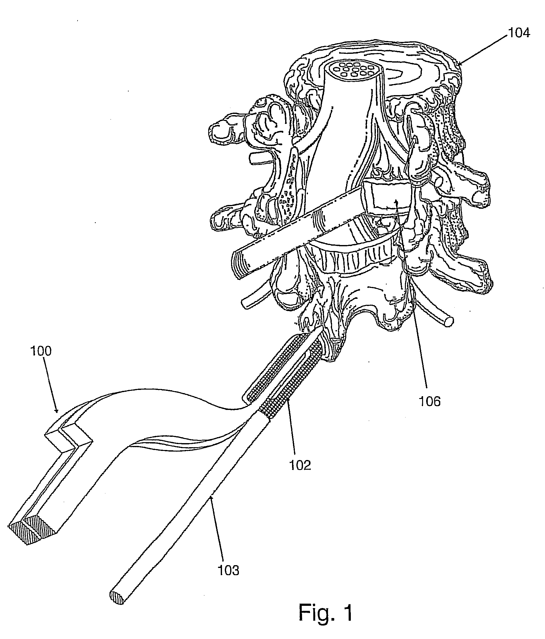
[0053]In an exemplary embodiment shown in FIG. 1, a system and method for spinal inserts is shown. In this figure a posterior view is shown with a dural sac retracted to the left, showing that a partial discectomy has been performed. In this exemplary embodiment, distractor 100 may fit around spinal insert 102 and, when inserted into a spinal column, act to separate two vertebrae by opening in a parallel fashion, allowing for the insertion of spinal insert 102. Rod or inserter 103 may be inserted into spinal insert 102. Insert 102 may have, for example, a threaded hole that accepts threading disposed on a distal end of rod 103. Rod 103 may act to hold insert 102 in place prior to its insertion in a spinal column and may also act to help position and orient insert 102 during its placing. Distractor 100 may then be positioned such that it is in line with disc space 106 in spinal column 104. Disc space 106 may be a hole formed between two vertebrae of a in a human spinal cord or thecal...


PUM


Abstract

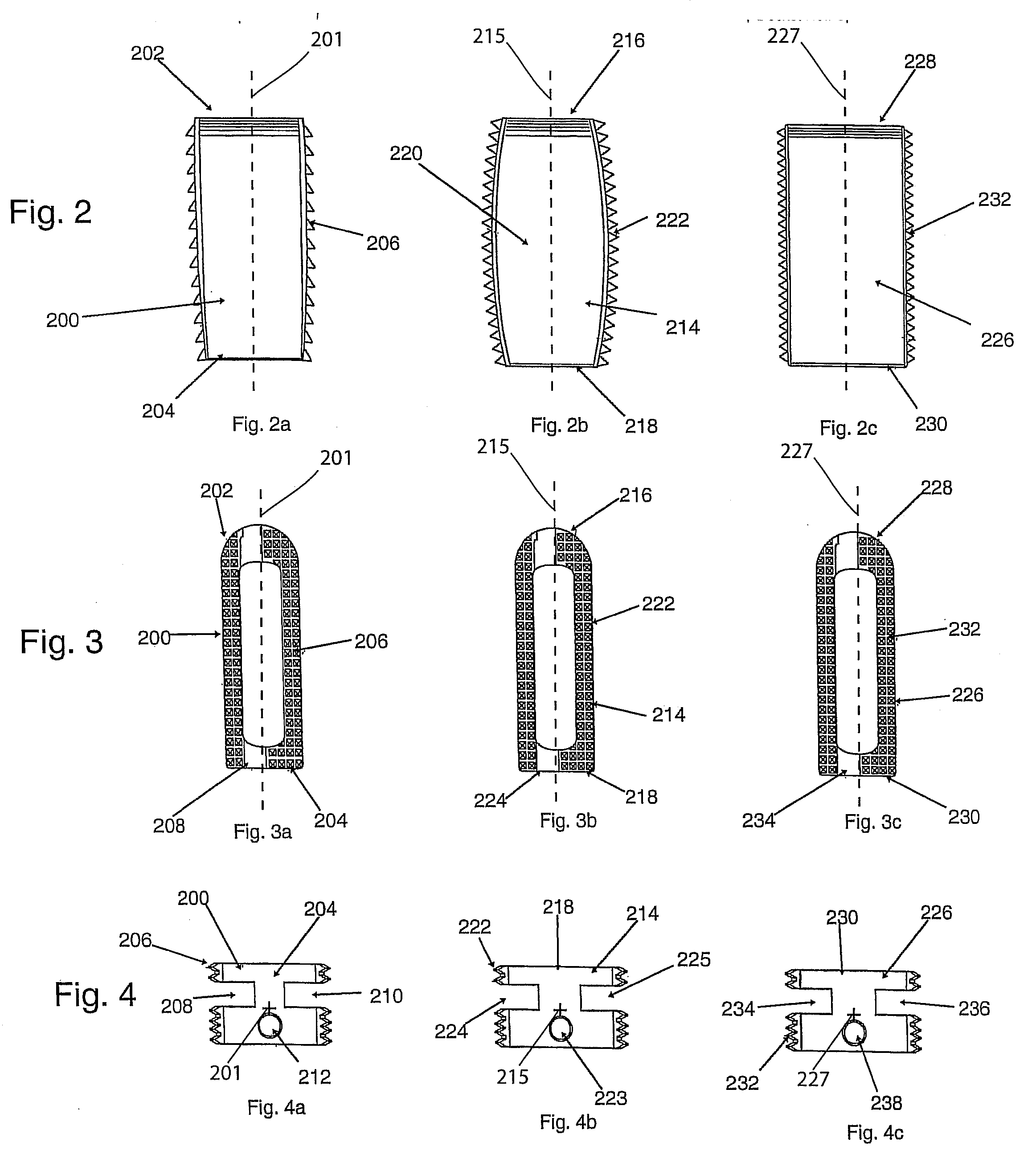
An apparatus, method and system for the treatment and management of spinal defects and inserting a spinal implant into an implantation space is described. The system may include a slotted implant, a distractor and an inserter and be employed in posterior lumbar or thoracic surgery.

Description

[0001]This application is a continuation of U.S. patent application Ser. No. 11 / 405,633, filed on Apr. 18, 2006 which claims the priority benefit under 35 U.S.C. 119 of U.S. provisional application No. 60 / 672,544 filed Apr. 19, 2005 the disclosure of which are hereby incorporated by reference in their entireties.FIELD OF THE INVENTION[0002]The present invention relates to apparatus, method and system for the treatment and management of spinal defects.BACKGROUND OF THE INVENTION[0003]The treatment and management of spinal defects remains one of the most challenging aspects of medicine. Spinal defects occur in a wide variety of clinical situations. They may result from spondylosis, tumor or even trauma. Preserving natural spinal motion and dynamics remains a considerable challenge. Maintaining or improving spinal sagittal balance should in theory allow the spine to be repaired at the level of correction and prevent adjacent level disease. Therefore, preserving spinal anatomy and stabi...

Claims


Application Information

Patent Timeline
Patent Type & Authority Applications(United States)
IPC IPC(8): A61B17/56
CPCA61B17/025A61F2310/00029A61F2/447A61F2/4611A61F2002/30079A61F2002/305A61F2002/30598A61F2002/30785A61F2002/3082A61F2002/30843A61F2002/30904A61F2002/4475A61F2002/4622A61F2002/4627A61F2002/4629A61F2210/009A61F2220/0025A61F2310/00023A61B2017/0256A61F2002/30594A61F2002/30593
Inventor PANNU, YASHDIP S.
Owner PANNU YASHDIP S
Learn More