
Cable modem and method of performing channel bonding using digital upconverter

a technology of channel bonding and upconverter, which is applied in the direction of digital transmission, duplex signal operation, selective content distribution, etc., can solve the problems of increasing the complexity of cable modems, and the error generated when the plurality of analog-frequency converters convert a frequency may not be significantly reduced, so as to reduce the complexity of rf processors and reduce the error generated

Inactive Publication Date: 2010-06-24
ELECTRONICS & TELECOMM RES INST
View PDF2 Cites 20 Cited by
  • Summary
  • Abstract
  • Description
  • Claims
  • Application Information

AI Technical Summary

Benefits of technology

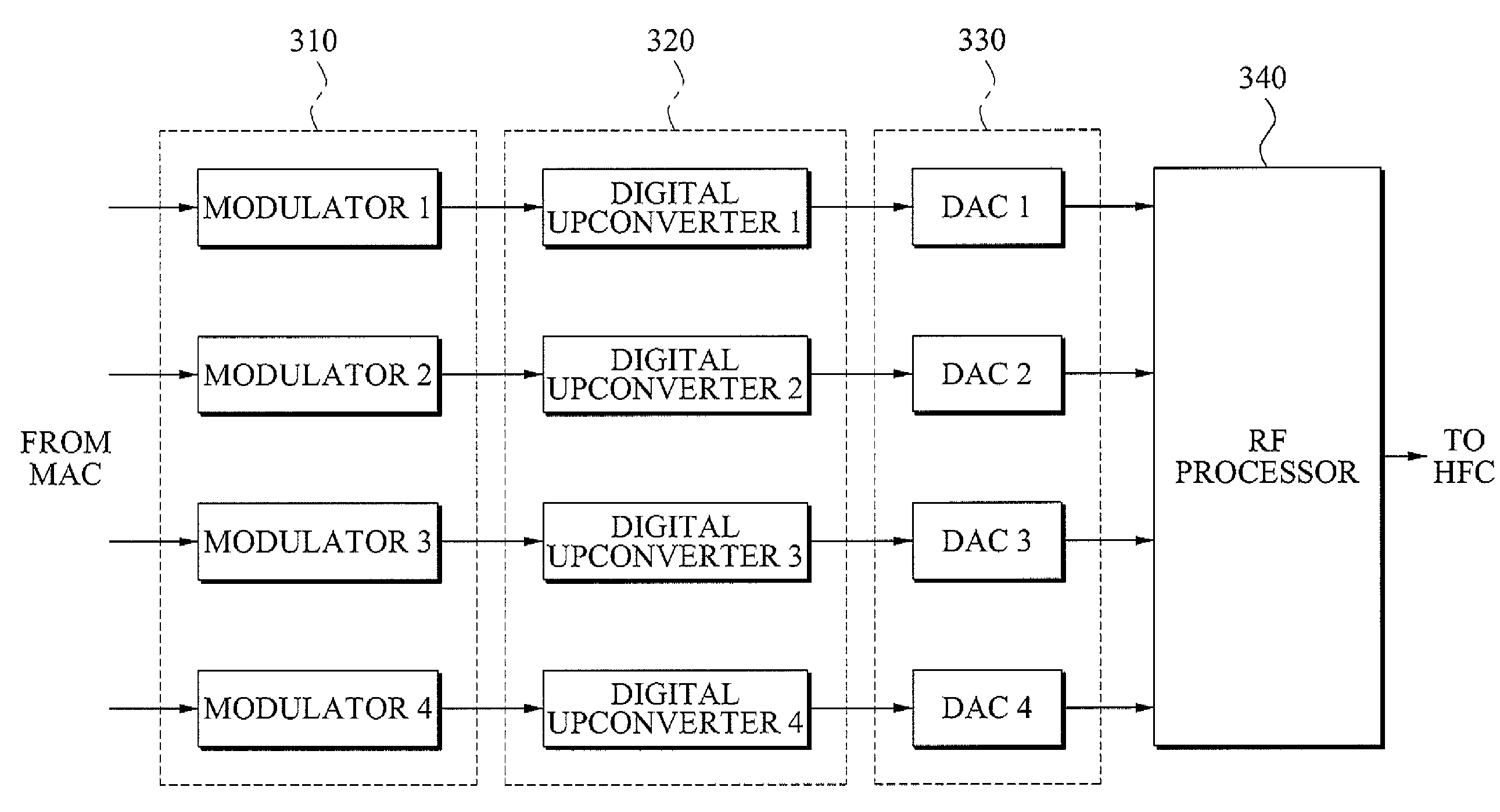
[0009]The present invention provides a cable modem which includes a digital upconverter up-converting a frequency of digital data in a previous stage of a Radio Frequency (RF) processor, and thereby may reduce a complexity of the RF processor.
[0010]The present invention also provides a cable modem which up-converts a frequency of digital data using a digital upconverter, and thereby may reduce an error generated when an RF processor converts a frequency.
[0012]The plurality of digital upconverters may up-convert the frequency of each of the plurality of pieces of digital data before the RF processor generates the analog output signal, and thus a configuration of the RF processor may be simple and an error generated when a frequency is converted may be reduced.
[0015]According to the present invention, a cable modem may include a digital upconverter up-converting a frequency of digital data in a previous stage of an RF processor, and thereby may reduce a complexity of the RF processor.
[0016]Also, according to the present invention, a cable modem may up-convert a frequency of digital data using a digital upconverter, and thereby may reduce an error generated when an RF processor converts a frequency.

Problems solved by technology

However, a plurality of analog-frequency converters may cause the increase in complexity of a cable modem.
Also, an error generated when the plurality of analog-frequency converters converts a frequency may not be significantly reduced.

Method used


Image

  • Cable modem and method of performing channel bonding using digital upconverter
  • Cable modem and method of performing channel bonding using digital upconverter
  • Cable modem and method of performing channel bonding using digital upconverter

Examples


Embodiment Construction

[0024]Reference will now be made in detail to exemplary embodiments of the present invention, examples of which are illustrated in the accompanying drawings, wherein like reference numerals refer to the like elements throughout. The exemplary embodiments are described below in order to explain the present invention by referring to the figures.

[0025]FIG. 1 is a diagram illustrating a general cable modem using a single channel.

[0026]Referring to FIG. 1, the cable modem using a single channel may include a modulator 110, a Digital-to-Analog Converter (DAC) 120, and a Radio Frequency (RF) processor 130.

[0027]The modulator 110 may modulate source data according to a predetermined modulation scheme and generate digital data. Also, the generated digital data may be provided to the DAC 120.

[0028]The DAC 120 may convert the digital data into an analog output signal. Also, the RF processor 130 may up-convert a frequency of the analog output signal into an RF range, generate a final output sig...


PUM


Abstract

A cable modem is provided. The cable modem may include: a plurality of modulators to generate a plurality of pieces of digital data corresponding to a plurality of independent channels; a plurality of digital upconverters to up-convert a frequency of each of the plurality of pieces of digital data into a predetermined frequency; and a Radio Frequency (RF) processor to channel-bond outputs of the plurality of digital upconverters into at least one channel, and generate an analog output signal, the outputs having the predetermined frequency.

Description

CROSS-REFERENCE TO RELATED APPLICATION[0001]This application claims priority from Korean Patent Application No. 10-2008-0130232, filed on Dec. 19, 2008, in the Korean Intellectual Property Office, the entire disclosure of which is incorporated herein by reference.BACKGROUND OF THE INVENTION[0002]1. Field of the Invention[0003]The present invention relates to a cable modem performing channel bonding, and more particularly, to a cable modem transmitting in an upstream in a Hybrid Fiber Coaxial (HFC) network.[0004]2. Description of Related Art[0005]A Data Over Cable Service Interface Specification (DOCSIS) 3.0 has been provided. This standard may support a downlink transmission rate of 150 Mbps and an uplink transmission rate of over 120 Mbps in a Hybrid Fiber Coaxial (HFC) network.[0006]A channel bonding technology is used to increase an uplink transmission speed up to over 120 Mbps. That is, a channel bonding technology may enable a plurality of independent channels to be channel-bon...

Claims


Application Information

Patent Timeline
IPC IPC(8): H04B1/38
CPCH04L12/2801H04N21/4382H04N21/2383H04L27/10H04L65/00
Inventor KIM, YANG SUSONG, YUN JEONGLEE, SOO IN
Owner ELECTRONICS & TELECOMM RES INST
Learn More