
Photovoltaic and fuel cell hybrid generation system using single converter and single inverter, and method of controlling the same

Inactive Publication Date: 2010-06-24
SAMSUNG ELECTRO MECHANICS CO LTD +1
View PDF6 Cites 67 Cited by
  • Summary
  • Abstract
  • Description
  • Claims
  • Application Information

AI Technical Summary

Benefits of technology

[0013]An aspect of the present invention provides a PV-FC hybrid generation system using a single converter and a single inverter, capable of achieving a reduction in the number of costly converters and inverters being used so that the size and manufacturing cost can be reduced and efficient system configuration is realized, and a method of controlling the same.

Problems solved by technology

However, photovoltaic cells have the following limitations: generating power only in the daytime, working as intermittent generation sources dependent upon environmental conditions such as cloud cover and rain, and having the very low maximum efficiency of approximately 10% to 15%.
However, PV-Battery hybrid systems are disadvantageous in that a battery is not a power generation device, but rather a secondary cell having a short useful lifespan that causes pollution during the manufacturing and discarding process.
PV-Wind hybrid systems also have disadvantages in that a wind power generation source is an intermittent power generation source that is dependent upon environmental conditions, and is not suitable for home use due to its restrictions in terms of installation space and noise.
As for PV-Diesel hybrid systems, a fossil fuel needs to be used and this places a limit on its development into an ultimate future power generation system.
This results in increases in manufacturing cost and size, obstructing the realization of a practical hybrid generation system.

Method used


Image

  • Photovoltaic and fuel cell hybrid generation system using single converter and single inverter, and method of controlling the same
  • Photovoltaic and fuel cell hybrid generation system using single converter and single inverter, and method of controlling the same
  • Photovoltaic and fuel cell hybrid generation system using single converter and single inverter, and method of controlling the same

Examples


Embodiment Construction

[0049]Exemplary embodiments of the present invention will now be described in detail with reference to the accompanying drawings.

[0050]The invention may, however, be embodied in many different forms and should not be construed as being limited to the embodiments set forth herein. Rather, these embodiments are provided so that this disclosure will be thorough and complete, and will fully convey the scope of the invention to those skilled in the art. Like reference numerals in the drawings denote like elements.

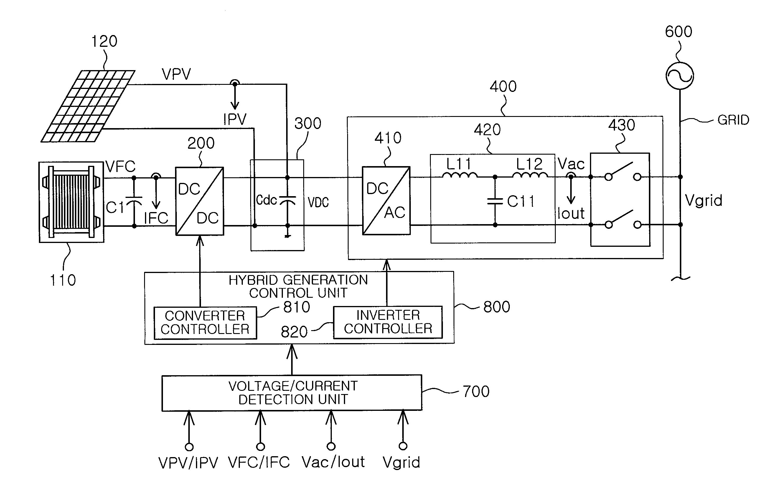
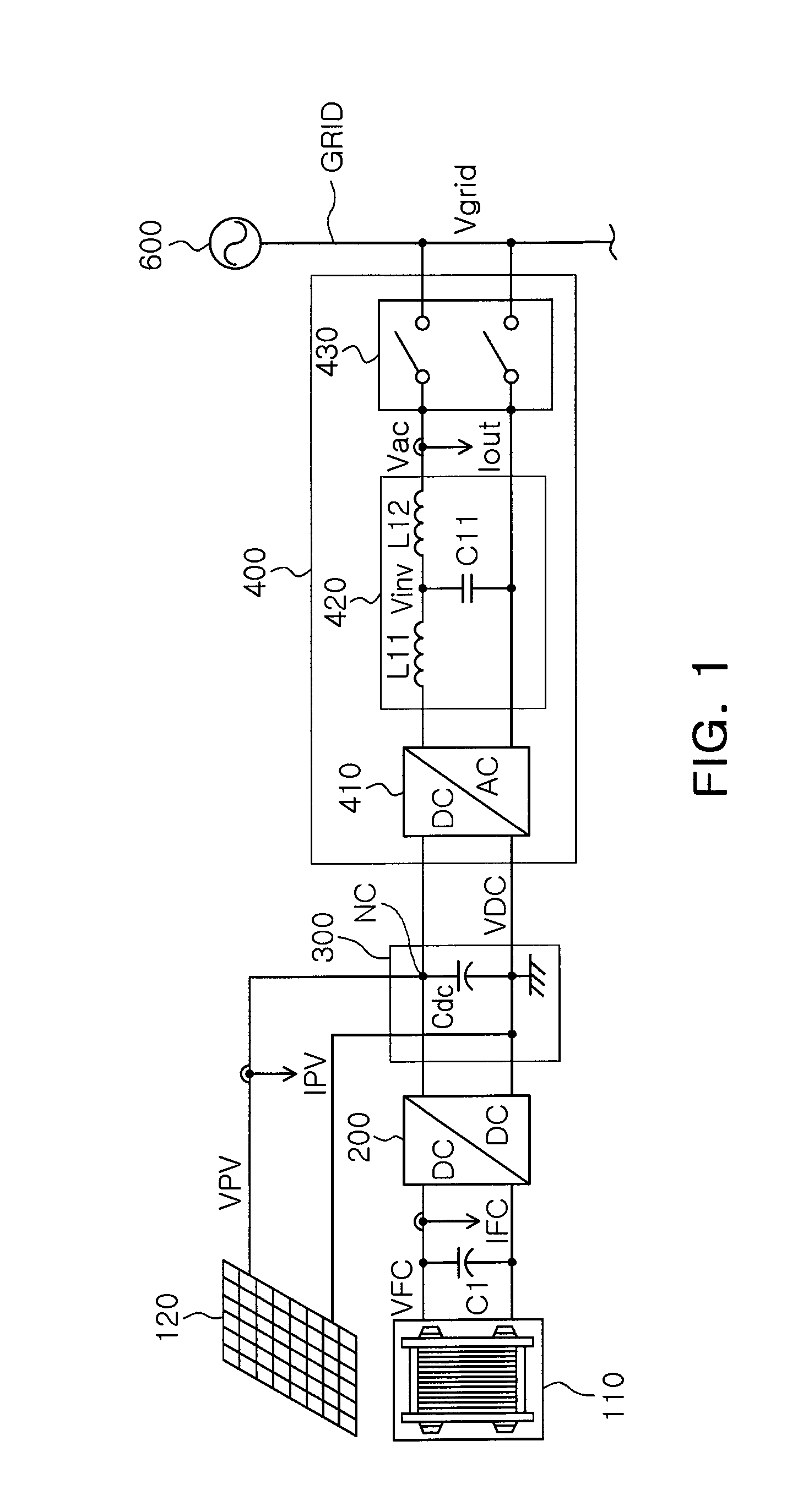
[0051]FIG. 1 is a circuit block diagram illustrating a PV-FC hybrid generation system using a single converter and a single inverter according to an exemplary embodiment of the present invention.

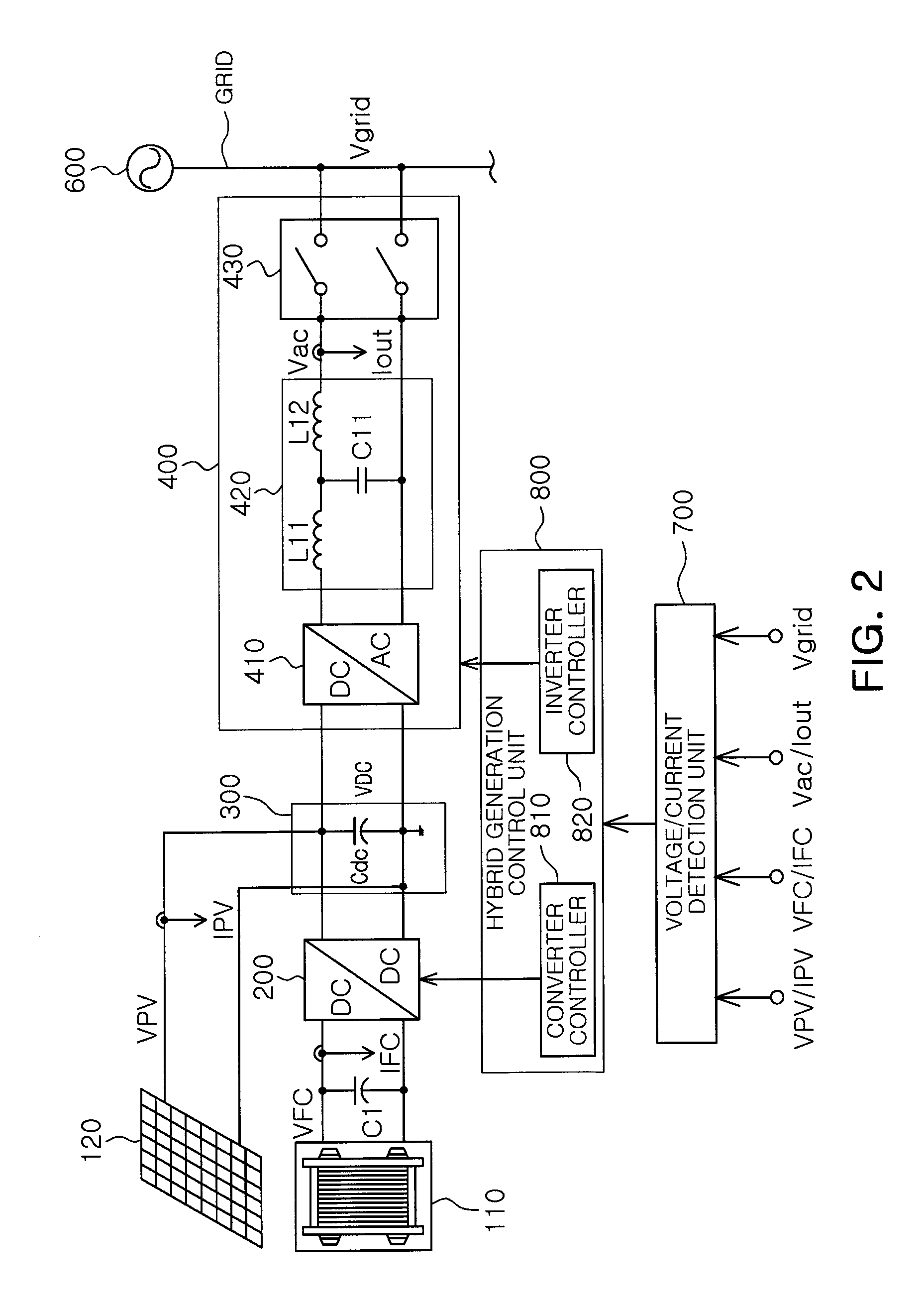
[0052]Referring to FIG. 1, a PV-FC hybrid generation system, according to this embodiment, may include a DC / DC converter unit 200, a DC link unit 300, and a DC / AC converter part 400. Here, the DC / DC converter unit 200 converts an FC output voltage VFC from a fuel cell 110, which converts...


PUM


Abstract

There are disclosed a photovoltaic and fuel cell (PV-FC) hybrid generation system using a single converter and a single inverter, and a method of controlling the same. The PV-FC hybrid generation system includes a DC / DC converter unit converting an FC output voltage from a fuel cell, converting chemical energy into electrical energy, into a preset voltage, a DC link unit commonly connecting an output terminal of a photovoltaic cell, converting the sunlight into electrical energy, and an output terminal of the DC / DC converter unit, and linking the converted FC output voltage from the DC / DC converter unit with a PV output voltage from the photovoltaic cell to thereby generate a DC voltage, and a DC / AC inverter unit converting the DC voltage from the DC link unit into a preset AC voltage. Furthermore, a method of controlling the PV-FC hybrid generation system is proposed.

Description

CROSS-REFERENCE TO RELATED APPLICATIONS[0001]This application claims the priority of Korean Patent Application Nos. 10-2008-0132663 filed on Dec. 23, 2008 and 10-2009-0115332 filed on Nov. 26, 2009, in the Korean Intellectual Property Office, the disclosures of which are incorporated herein by reference.BACKGROUND OF THE INVENTION[0002]1. Field of the Invention[0003]The present invention relates to a photovoltaic and fuel cell hybrid generation system (hereinafter “PV-FC hybrid generation system”), and a method of controlling the same, and more particularly, to a PV-FC hybrid generation system using a single converter and a single inverter, which achieves a reduction in the number of costly converters and inverters required, and a method of controlling the same.[0004]2. Description of the Related Art[0005]Since the late 20th century, the demand for developing renewable energy sources has increased due to the depletion of fossil fuels, and the environmental pollution and global warmi...

Claims


Application Information

Patent Timeline
IPC IPC(8): H02J3/38
CPCH01M16/003H02J3/387H02J2001/004H02S10/10H02J3/383H02J3/386Y02E10/763Y02E10/563H02J2300/30H02J2300/28H02J2300/24H02J3/381Y02E10/56Y02E10/76Y02E60/50H02J3/46H02J3/44
Inventor KIM, JIN WOOKLEE, BYOUNG KUKKIM, JONG SOOCHOE, GYU YEONGKIM, JONG SUNLEE, IL WOONWON, JAE SUNKIM, JONG HAEOH, DONG SEONG
Owner SAMSUNG ELECTRO MECHANICS CO LTD
Learn More