
Method of Designing a Bottom Hole Assembly and a Bottom Hole Assembly

a design method and technology for bottom holes, applied in earth drilling, metal-working drilling tools, manufacturing tools, etc., can solve the problems of requiring significant time, effort and expense, and drilling a borehole for the recovery of hydrocarbons or minerals is typically very expensive, and the process, known as the “trip” of the drill string, is not easy to achiev

Inactive Publication Date: 2010-06-24
SMITH INT INC
View PDF47 Cites 79 Cited by
  • Summary
  • Abstract
  • Description
  • Claims
  • Application Information

AI Technical Summary

Benefits of technology

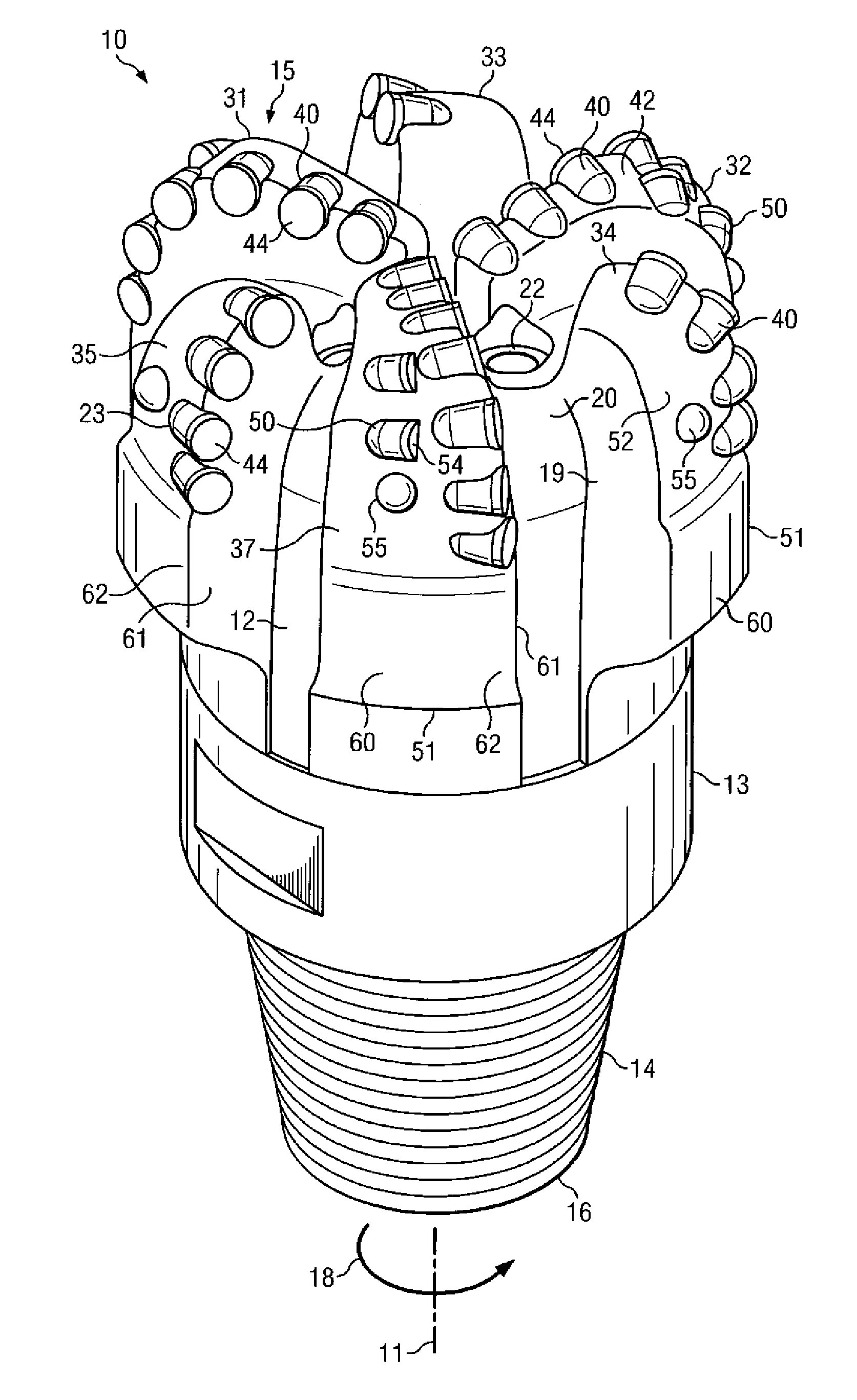
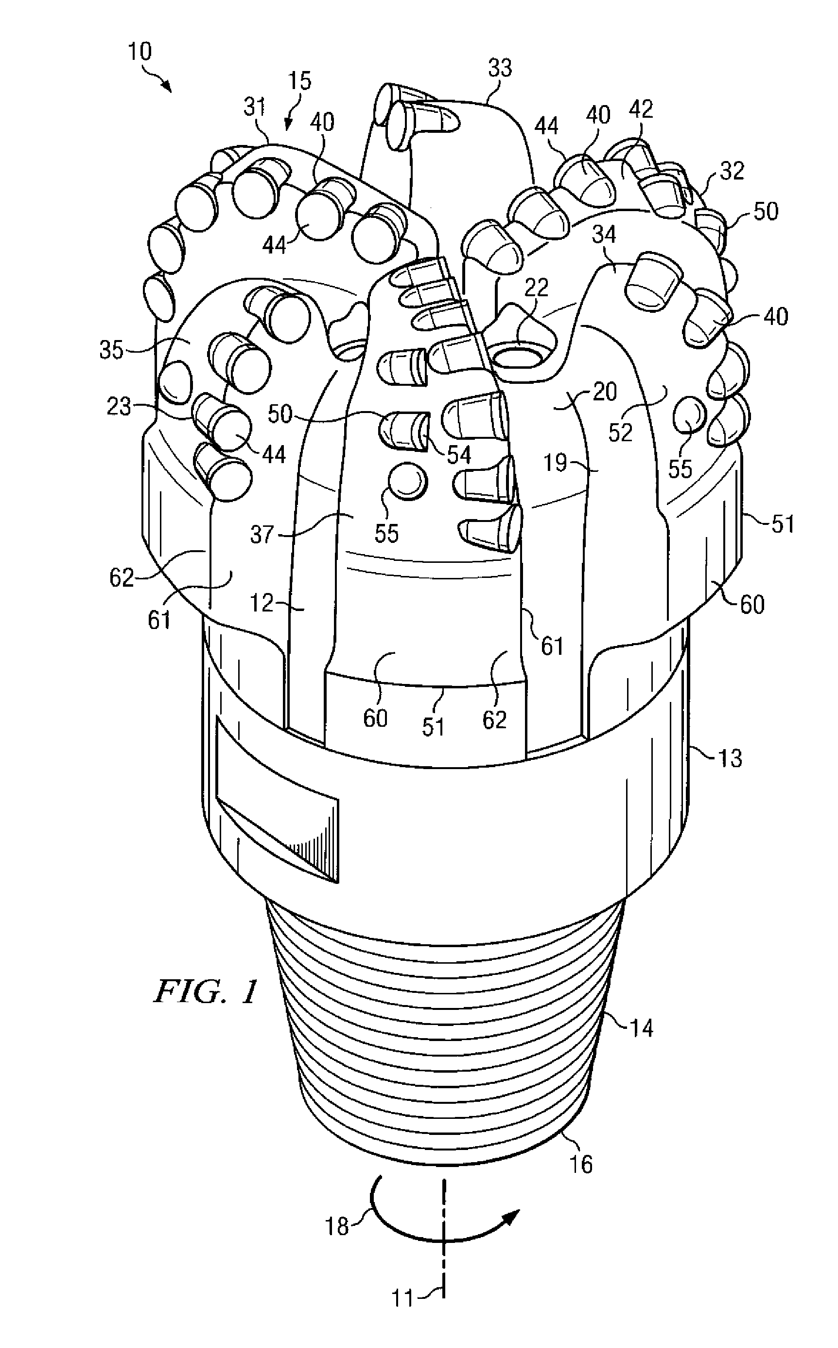
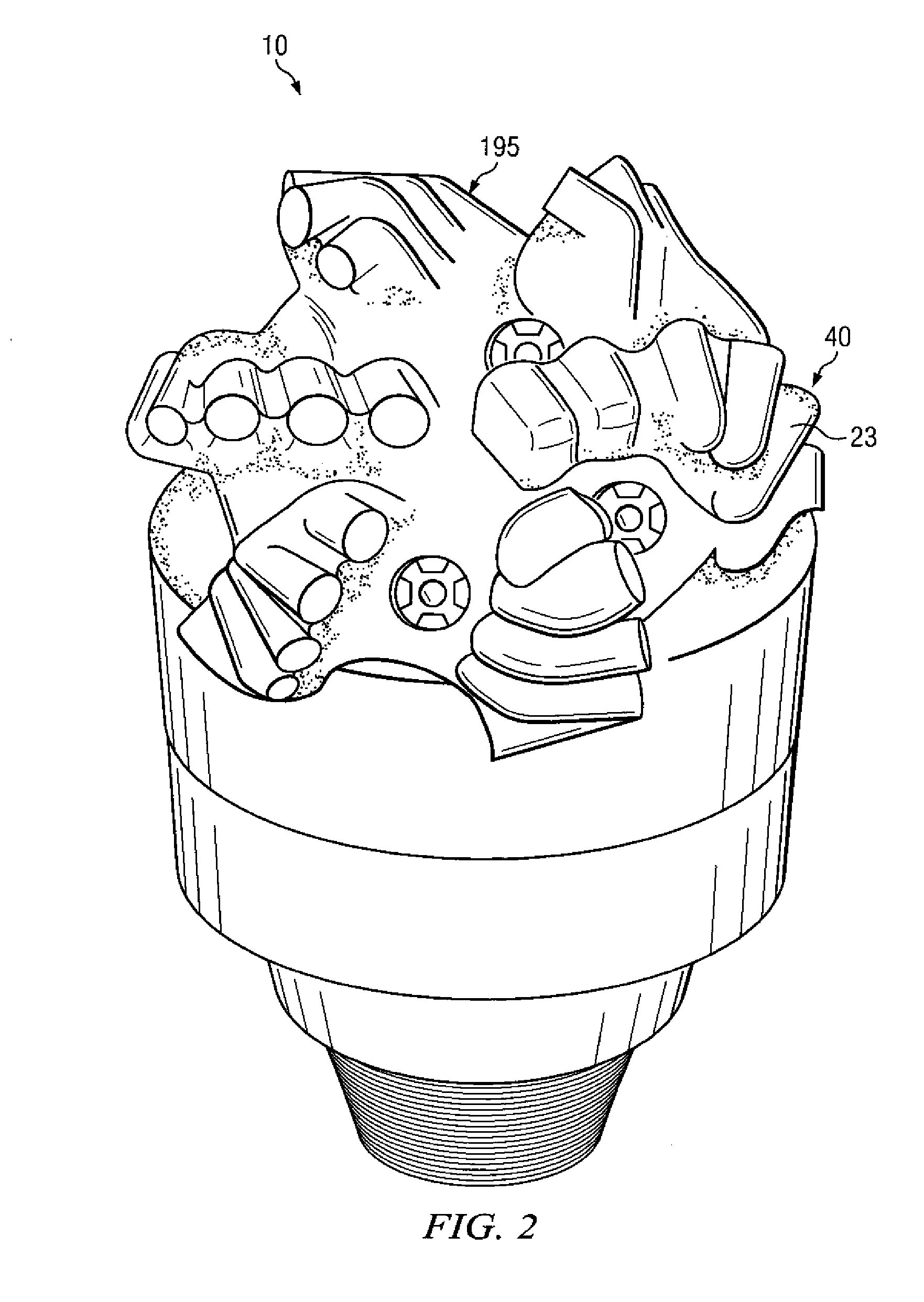
The present patent relates to a method for designing a bottom hole assembly, which includes a drill bit with cutter elements attached to it. The drill bit has different properties in different areas. The cutter elements are made of thermally stable polycrystalline diamond cutter elements containing a diamond body with interstitial regions that are substantially free of the catalyst material. The drill bit also has primary blades and a plurality of primary cutter elements mounted on them. The cutter elements are arranged on the bit body based on its properties and the cutter element properties. The drill bit is designed to improve its performance in drilling boreholes in earthen formations.

Problems solved by technology

Drilling a borehole for the recovery of hydrocarbons or minerals is typically very expensive due to the high cost of the equipment and personnel that are required to safely and effectively drill to the desired depth and location.
A bit may need to be changed because of wear or breakage.
As is thus obvious, this process, known as a “trip” of the drill string, requires considerable time, effort, and expense.
The whirling subjects the cutter elements on the bit to increased load, impact and wear, which can cause premature failure of the cutter elements and a loss of penetration rate.

Method used


Image

  • Method of Designing a Bottom Hole Assembly and a Bottom Hole Assembly
  • Method of Designing a Bottom Hole Assembly and a Bottom Hole Assembly
  • Method of Designing a Bottom Hole Assembly and a Bottom Hole Assembly

Examples


Embodiment Construction

[0028]In one aspect, the present disclosure provides for the design of drill bits and bottom hole assemblies with improved drilling efficiency and downhole drilling life by utilizing at least two different cutter elements and selectively positioning the different cutter elements at optimum locations based on the properties of the BHA and the properties of the cutter elements. Cutter elements may be manufactured in various configurations with a wide range of material properties. Selecting the optimum cutter element for different areas of a drill bit or bottom hole assembly can maximize performance as well as reduce cost.

[0029]The following disclosure is directed to various embodiments of the invention. The embodiments disclosed have broad application, and the discussion of any embodiment is meant only to be exemplary of that embodiment, and not intended to intimate that the scope of the disclosure, including the claims, is limited to that embodiment or to the features of that embodim...


PUM

PropertyMeasurementUnit
depthaaaaaaaaaa
pressuresaaaaaaaaaa
temperaturesaaaaaaaaaa

Abstract

A bottom hole assembly containing a drill bit. The drill bit additionally has a plurality of primary cutter elements mounted thereto. The plurality of cutter elements comprise one or more first cutter elements and one or more second cutter elements. The second cutter element differs from the first cutter element in at least one cutter element property. The first cutter element has a diamond body containing a first region comprising an infiltrant material disposed within the interstitial regions. The first region is located remote from the working surface of the diamond body. The first cutter element also contains a second region comprising interstitial regions that are substantially free of the infiltrant material. The second region is located along at least the working surface of the diamond body. Also included are a cutter element, method of designing a bottom hole assembly as well as method of designing a drill bit.

Description

CROSS-REFERENCE TO RELATED APPLICATIONS[0001]This application claims priority to U.S. Provisional Application No. 61 / 138,810, filed Dec. 18, 2008 and U.S. Provisional Application No. 61 / 143,875, filed Jan. 12, 2009, both of which are incorporated by reference in their entirety.FIELD OF THE INVENTION[0002]The invention relates to bottom hole assemblies used to form wellbores in earthen formations and more particularly, the arrangement of cutter elements on the bottom hole assembly using two or more different cutter elements.BACKGROUND OF THE INVENTION[0003]In a conventional drilling system for drilling an earthen formation, the drilling system includes a drilling rig used to turn a drilling tool assembly that extends downward into a wellbore. The drilling tool assembly includes a drill string and a bottom hole assembly (BHA). The drill string includes several joints of drill pipe connected end to end through tool joints. The drill string is used to transmit drilling fluid (through it...

Claims


Application Information

Patent Timeline
Patent Type & Authority Applications(United States)
IPC IPC(8): E21B10/55E21B10/42E21B10/43B21K5/04
CPCC22C26/00E21B10/43E21B10/36E21B10/567E21B10/55
Inventor KESHAVAN, MADAPUSI K.ZHANG, YOUHESHEN, YUELINCARIVEAU, PETER T.
Owner SMITH INT INC
Learn More