
Compound computer system and method for sharing PCI devices thereof

a computer system and computer technology, applied in the direction of electric digital data processing, instruments, etc., can solve the problems of insufficient number of i/o devices per computer, insufficient number of i/o devices connected to one computer, etc., and achieve the effect of convenient setting

Inactive Publication Date: 2010-06-17
HITACHI LTD
View PDF0 Cites 36 Cited by
  • Summary
  • Abstract
  • Description
  • Claims
  • Application Information

AI Technical Summary

Benefits of technology

[0015]This invention has been made to solve the above-mentioned problem, and therefore, it is an object of this invention to arbitrate, when one I / O device is shared by a plurality of computers, failure handlings carried out by the respective computers at an occurrence of a failure in the I / O device, among the computers, to thereby carry out the failure handlings without affecting other computers sharing the I / O device.
[0018]Further, when forming a computer (or switching, when an I / O device fails, to another I / O device), the content information of the failure recovery process (failure handling) is contained in the profile information on a computer set in advance, and the resource management module selects a computer and an I / O device, based on the content information of the failure recovery process, considering the content of the failure handling. Accordingly, the configuration for sharing the multi-root I / O device by a plurality of computers may be easily set with consideration given to the failure recovery process.

Problems solved by technology

While a plurality of serves operate on one computer, the number of I / O devices which are connectable to the one computer has not increased due to physical constraint, and the number of I / O devices per computer is relatively insufficient.

Method used


Image

  • Compound computer system and method for sharing PCI devices thereof
  • Compound computer system and method for sharing PCI devices thereof
  • Compound computer system and method for sharing PCI devices thereof

Examples


first embodiment

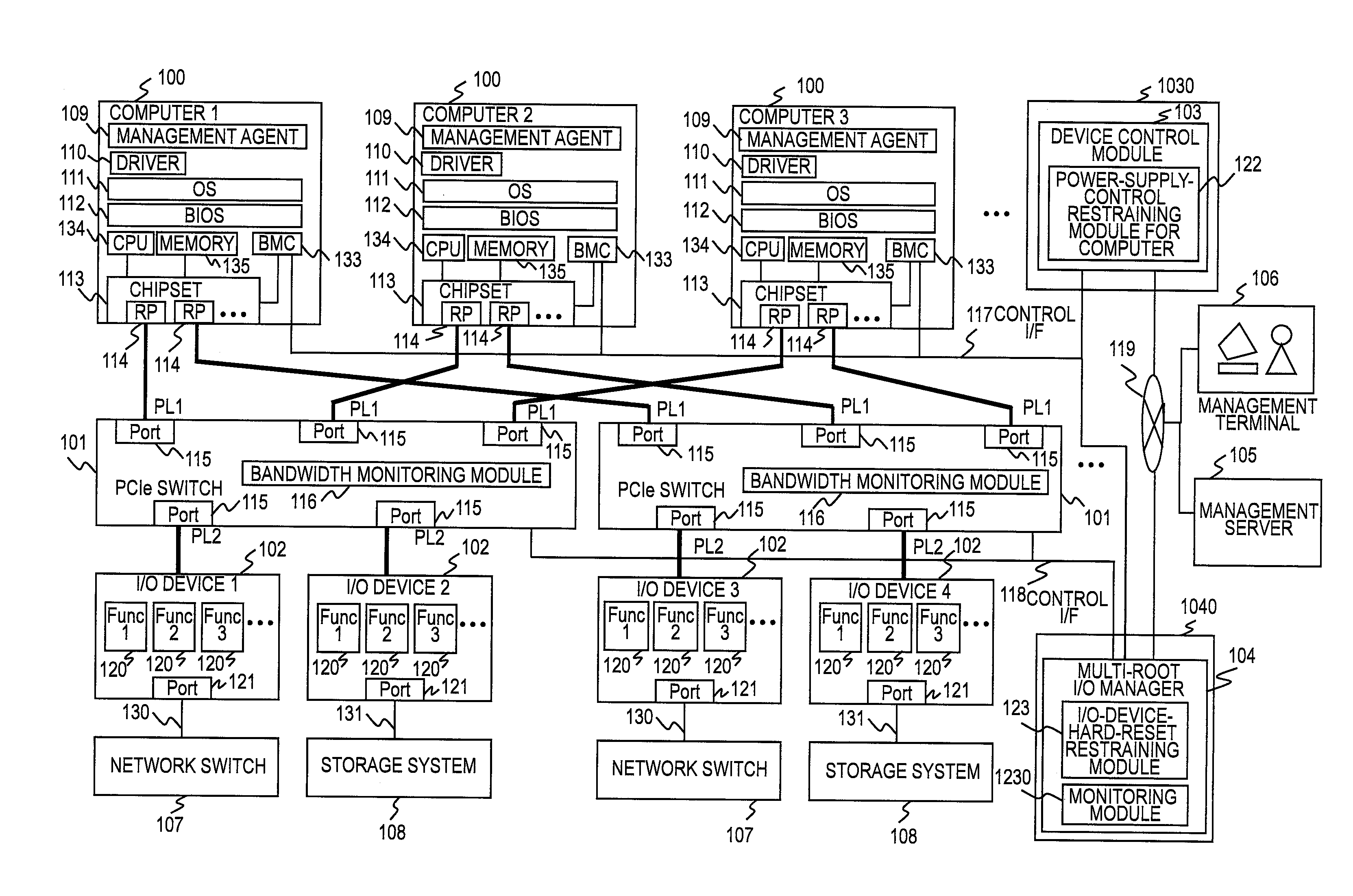
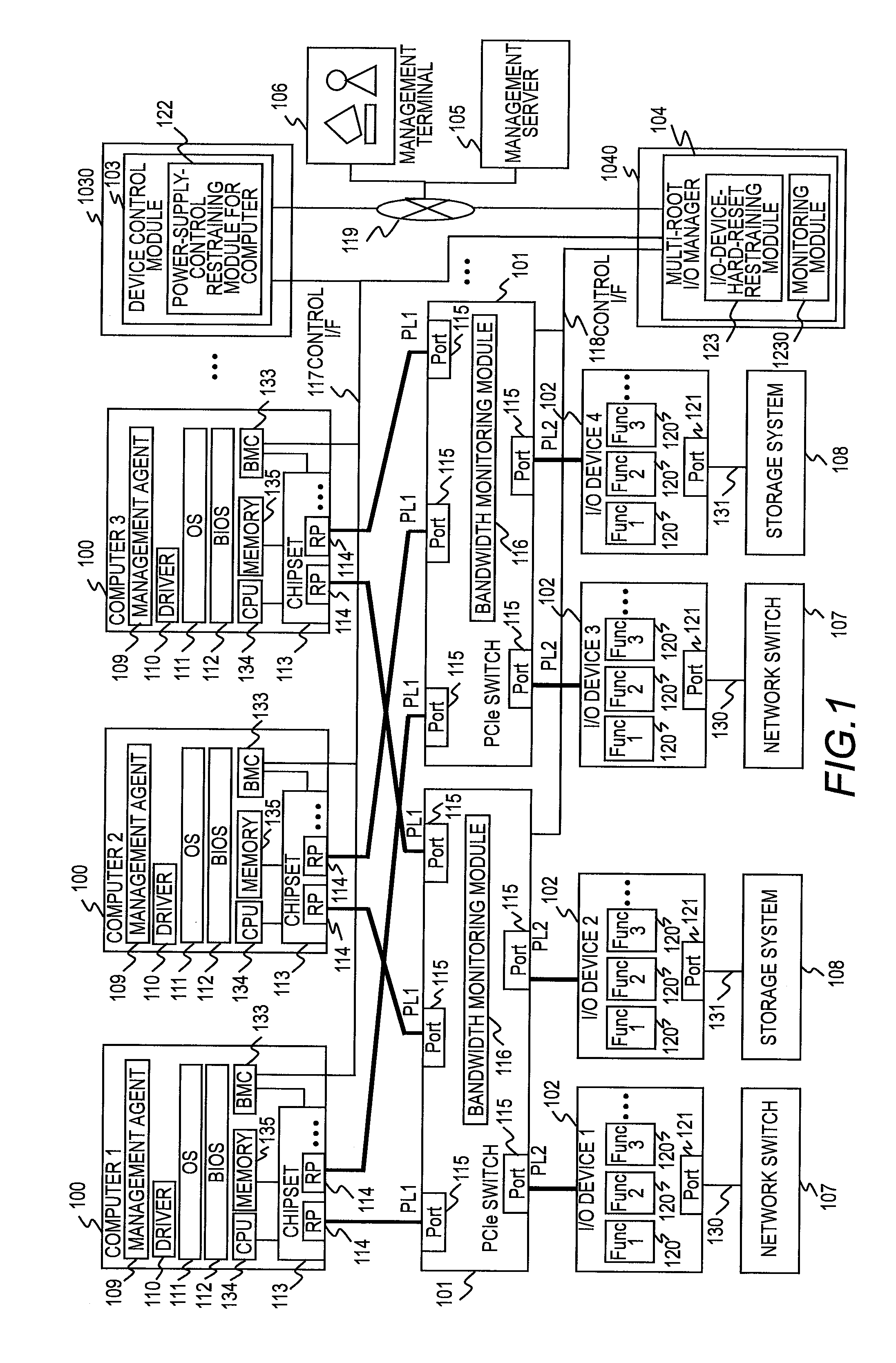
[0044]First, a description is given of a configuration of a compound computer system according to a first embodiment of this invention. FIG. 1 is a block diagram of the compound computer system according to the first embodiment of this invention.

[0045]As illustrated in FIG. 1, the compound computer system according to this embodiment includes at least one multi-root PCI Express switch 101 which is capable of mutually connecting at least one computer 100 and a plurality of multi-root I / O devices 102 with each other, at least one multi-root I / O device 102 for assigning Functions 120 set in advance to different computers 100 for sharing, a device control computer 1030 for executing a device control module 103 in order to provide power supply control and the like of the computers 100, a switch management computer 1040 for executing a multi-root I / O manager 104 for providing control such as initialization of the multi-root PCI Express switches 101 and the multi-root I / O devices 102, sett...

second embodiment

[0147]A description is given of a configuration of a compound computer system according to a second embodiment of this invention. The compound computer system according to the second embodiment is the same as the compound computer system according to the first embodiment of this invention illustrated in FIG. 1 except for the I / O device management information 128 illustrated in FIG. 3 and the failure handling methods employed by the resource management software 132 at an occurrence of a failure in an I / O device in the compound computer system illustrated in FIG. 9. Thus, a description is given below of only the portions different from these according to the first embodiment, and a description is not given of the same portions.

[0148]FIG. 17 illustrates an example of the I / O device management information 128 held by the management server 105 of the compound computer system according to the second embodiment.

[0149]As illustrated in FIG. 17, the I / O device management information 128 repr...

third embodiment

[0156]A description is given of a configuration of a compound computer system according to a third embodiment of this invention. The compound computer system according to the third embodiment is the same as the compound computer system according to the first embodiment of this invention illustrated in FIG. 1 except for the hard reset control of an I / O device performed by the multi-root I / O manager 104. Thus, a description is given below of only the portions different from these according to the first embodiment, and a description will not given of the same portions.

[0157]FIG. 19 is a flowchart illustrating an example of the hard reset control method of an I / O device of the compound computer system according to the third embodiment. According to the third embodiment, the control portion of the I / O device hard reset control (Step S407 of FIG. 5) by the multi-root I / O manager 104 illustrated in FIGS. 5, 6, and 8 according to the first embodiment is replaced by the control illustrated i...


PUM


Abstract

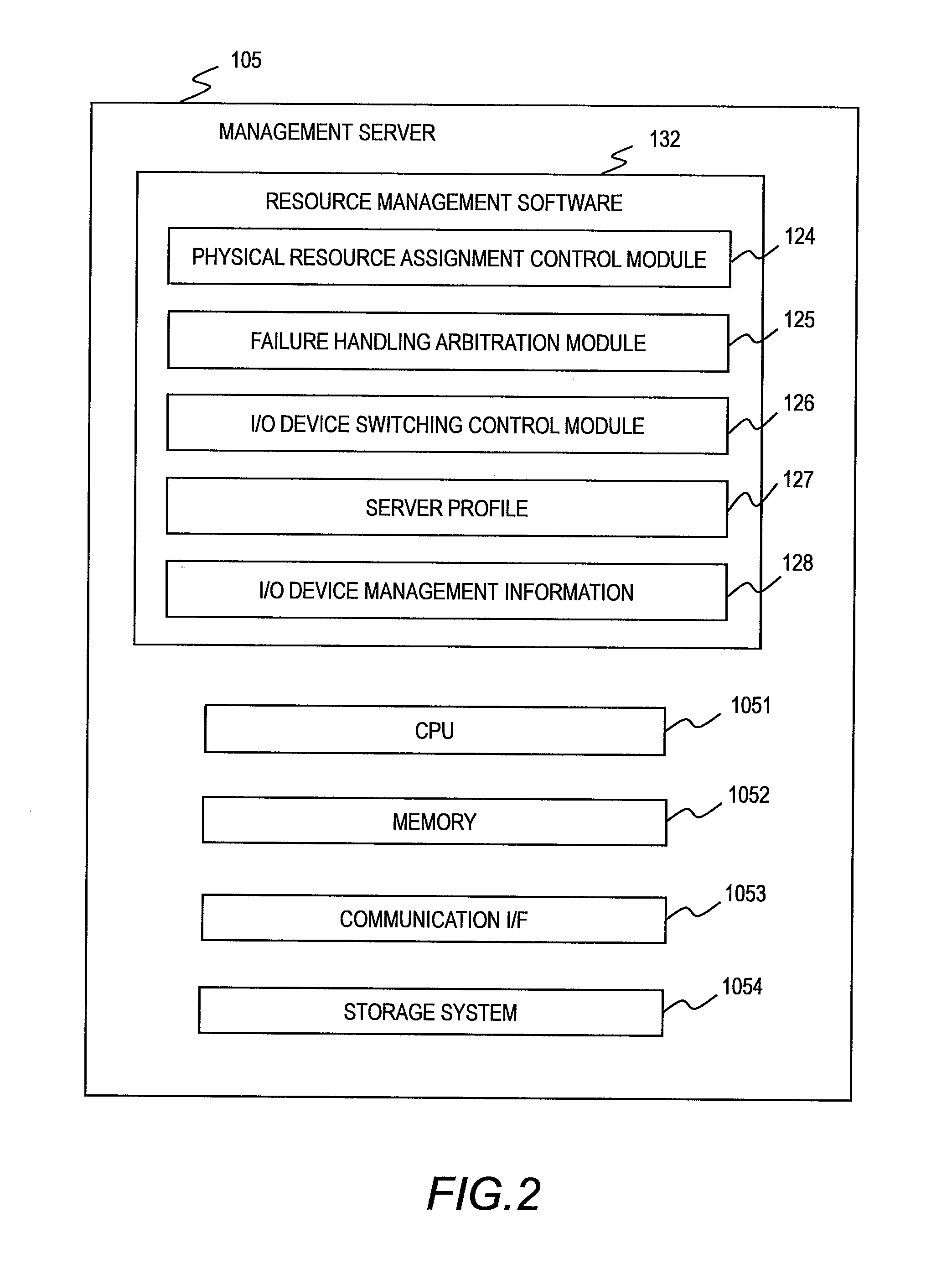
A resource management module of a management server for controlling a multi-root I / O manager connected to a PCI switch for connecting a plurality of I / O devices and a plurality of computers with each other includes: failure handling content information indicating, for each computer sharing a multi-root I / O device, a content of a failure handling at an occurrence of a failure in the multi-root I / O device; and failure handling availability status information indicating whether a hardware reset of the multi-root I / O device is possible and updates, upon reception of a notification of the occurrence of the failure in the multi-root I / O device, the failure handling availability status information, and instructs, based on the failure handling availability status information, the multi-root I / O manager to restrain or cancel the hardware reset of the multi-root I / O device.

Description

CLAIM OF PRIORITY[0001]The present application claims priority from Japanese patent application JP 2008-321136 filed on Dec. 17, 2008, the content of which is hereby incorporated by reference into this application.BACKGROUND OF THE INVENTION[0002]This invention relates to a device control technology for a compound computer system in which a plurality of computers and a plurality of I / O devices are connected with each other via peripheral component interconnect (PCI) switches, and more particularly, to control for handing a failure which has occurred in an I / O device shared by a plurality of computers.[0003]IT systems used for processing for task-related information in companies are configured by various servers including WEB servers for displaying information to users information on respective tasks, application (AP) servers for integrating and processing information, database (DB) servers for accumulating and storing information, and the like. Those servers use computers, each incl...

Claims


Application Information

Patent Timeline
IPC IPC(8): G06F13/00
CPCG06F13/4022
Inventor BABA, TAKASHIGEUEHARA, KEITAROTSUSHIMA, YUJI
Owner HITACHI LTD
Learn More