
Objective lens actuator, optical pickup and optical disc drive

a technology of optical pickup and actuator, which is applied in the manufacture of optical heads, instruments, data recording, etc., can solve the problems of deterioration of signal quality and deterioration of recording/reproducing on/from optical discs, and achieve the stability of recording/reproducing signals, reduce relative dynamic tilt between optical discs and optical pickups, and reduce data errors.

Inactive Publication Date: 2010-06-17
HITACHI MEDIA ELECTORONICS CO LTD
View PDF7 Cites 0 Cited by
  • Summary
  • Abstract
  • Description
  • Claims
  • Application Information

AI Technical Summary

Benefits of technology

[0011]The present invention is accomplished upon basis of the fact mentioned above, and an object thereof is to provide an objective lens actuator for enabling to reduce the dynamic relative tilt between the optical disc and the objective lens (i.e., to reduce the tile of the objective lens in the tangential direction when operating), as well as, an optical pickup and an optical disc drive.
[0013](2) For accomplishing the object mentioned above, according to the present invention, there is also provided an objective lens actuator, for driving an objective lens for focusing lights upon a recoding surface of an optical disc, comprising: a moving part, which comprises said objective lens and a coil; a magnet, which is fixed on a yoke and drives said moving part; a plural number, of elastic support parts, each of which supports said moving part at an end thereof; a first fixing portion and a second fixing portion, which fix other ends of said plural number of elastic support parts and are disposed opposite to each other in a focus direction; a third fixing portion, which is disposed between said first fixing portion an said second fixing portion; and a moving mechanism, which is provided on said first and second fixing portion, so that said first and second fixing portions can move in the focus direction, relatively, with respect to said third fixing portion.
[0020]According, to the present invention, it is possible to reduce the relative dynamic tilt between the optical disc and the optical pickup to be small. As a result of this, it is possible to achieve the optical disc drive, having stability of a recording / reproducing signal and less in data error, and the optical disc drive mounting this optical pickup can also obtain high reliability thereof.

Problems solved by technology

One of the reasons of the dynamic tilt of the objective lens lies in the unevenness of parts or assembling thereof.
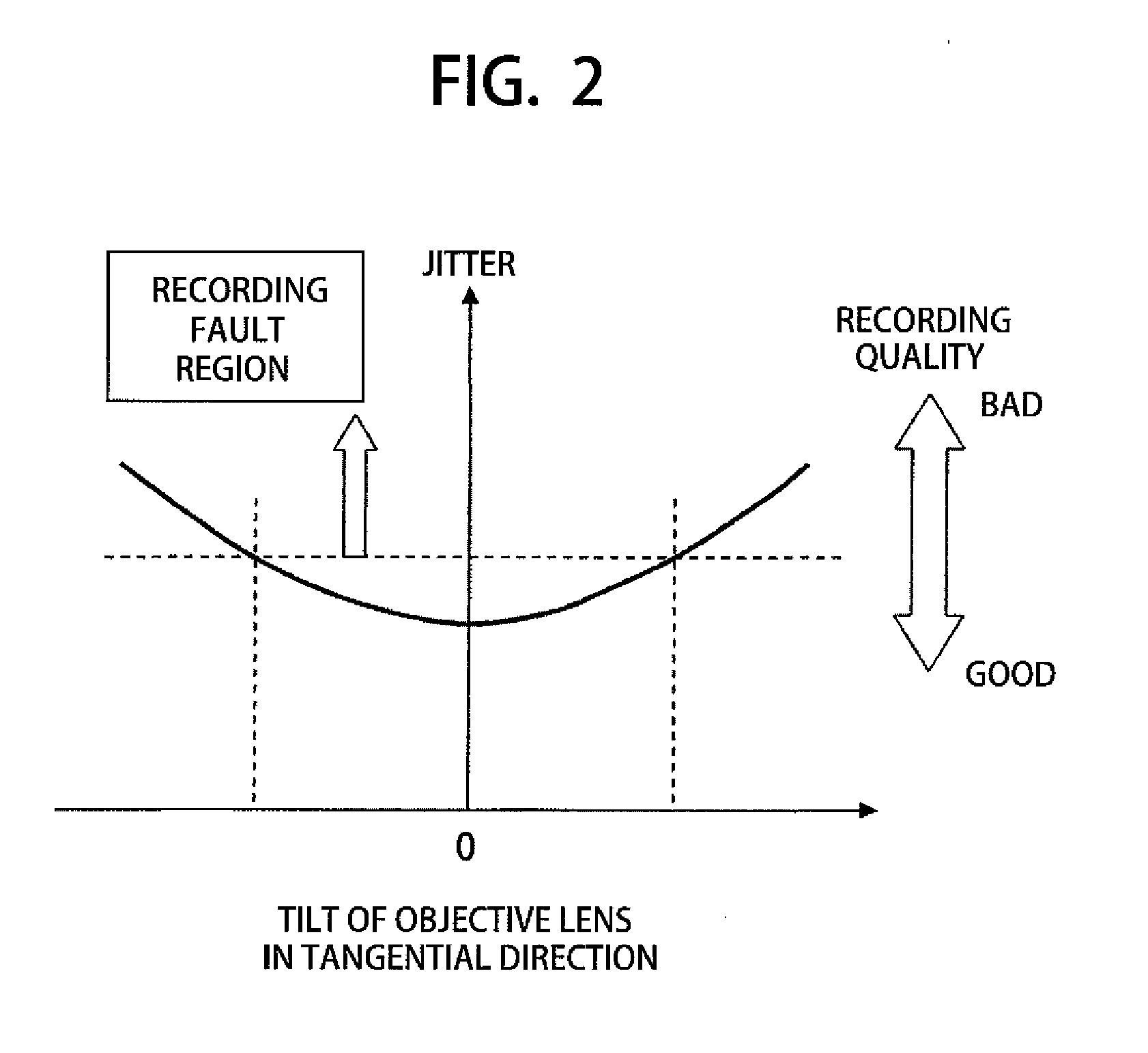
For that reason, a relative tilt is dynamically generated between the optical disc and the objective lens, and thereby light intensity distribution of the optical spot changes; this results into deterioration of the signals when recording / reproducing.
Also, with the tilt of the objective lens with respect to the optical disc, there is a problem that the quality of recording / reproducing onto / from an optical disc is deteriorated even if it is tilted in either the radial direction or the circumferential direction with respect to the optical disc.

Method used


Image

  • Objective lens actuator, optical pickup and optical disc drive
  • Objective lens actuator, optical pickup and optical disc drive
  • Objective lens actuator, optical pickup and optical disc drive

Examples


Embodiment Construction

[0035]Hereinafter, explanation will be made on an objective lens actuator, an optical pickup and an optical disc drive, according to the present invention, by referring to the attached drawings.

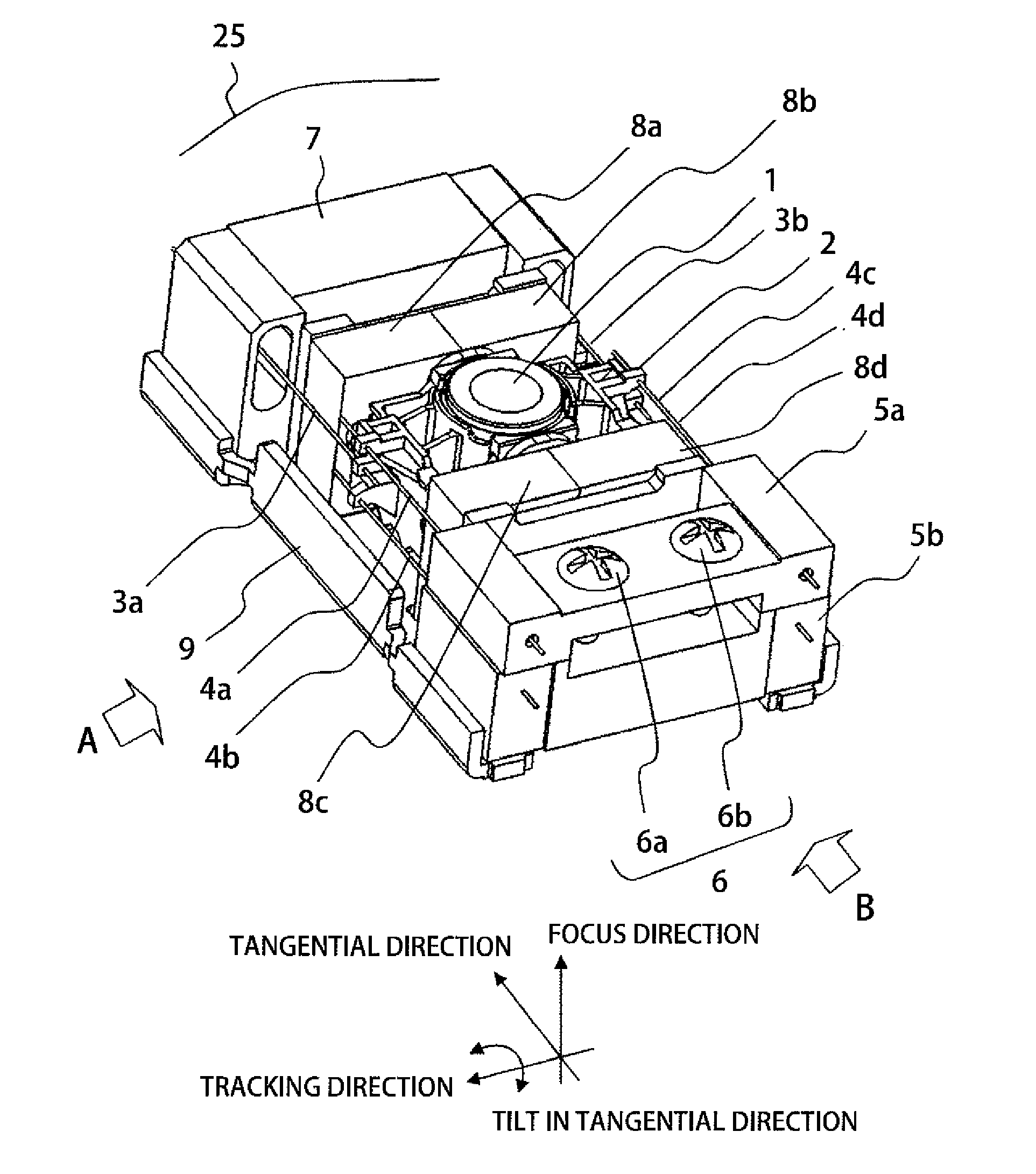
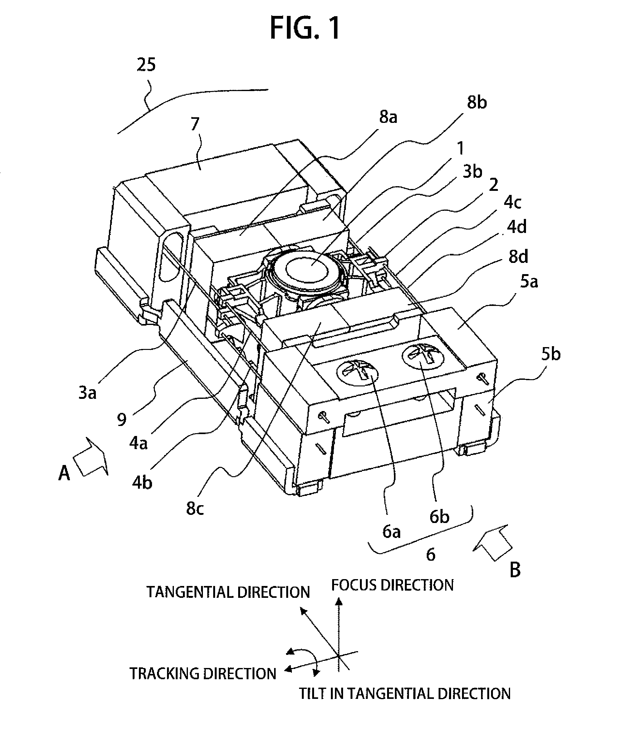
[0036]Explanation will be made on a first embodiment of the objective lens actuator according to the present invention, by referring to FIGS. 1 to 5 attached herewith. FIG. 1 is a perspective view for showing a first embodiment of an objective lens actuator, according to the present invention; FIG. 2 is a view for showing a jitter characteristic when an objective lens is tilted in a tangential direction of an optical disc with respect to an optical disc; FIG. 3 is a side view for showing a moving mechanism of a tilt wire fixing portion by means of screws, in the first embodiment of the objective lens actuator, in particular, shown by an arrow “B” in FIG. 1; FIGS. 4A to 4C are views for explaining correction action of the objective lens in the tangential direction, in the first embodiment of t...


PUM

PropertyMeasurementUnit
optical pickupaaaaaaaaaa
densityaaaaaaaaaa
elasticaaaaaaaaaa

Abstract

An objective lens actuator 25, for driving an objective lens 1 for focusing lights upon a recoding surface of an optical disc, comprises a moving part 2, which comprises the objective lens 1 and a coil; a magnet, which is fixed on a yoke and drives the moving part 2; a plural number of elastic support parts, each of which supports the moving part 2 at an end thereof; a first fixing portion 5a and a second fixing portion 5b, which fix other ends of the plural number of elastic support parts 4 and are disposed opposite to each other in a focus direction; and a moving mechanism 6, which is provided on the first and second fixing portion 5a and 5b, so that the first and second fixing portions 5a and 5b can move in the focus direction, relatively, and thereby providing the objective lens actuator 25 enabling to reduce the dynamic relative tilt between the optical disc and the objective lens 1 (i.e., reducing the tilt of the objective lens 1 in the tangential direction when operating), as well as, an optical pickup and an optical disc drive.

Description

BACKGROUND OF THE INVENTION[0001]The present invention relates to an objective lens actuator of an optical pickup for conducting reading / writing from / onto a disc within an optical disc drive, an optical pickup comprising this objective lens actuator therein, and an optical disc drive comprising this optical pickup therein.[0002]In recent years, advancement of high density is achieved in the optical discs, and as a method for dealing with that, mainly, wavelength of a laser is shortened or an aperture of an objective lens is enlarged. For this reason, ill influences upon the quality of an optical spot become large due to inclination of the objective lens with respect to the optical disc. Since deterioration of a signal of the optical spot due to the inclination of the objective lens is also linked up with the deterioration of a signal when recording / reproducing, there is brought about a necessity of suppressing a tilt between the optical disc and the objective lens.[0003]In such opti...

Claims


Application Information

Patent Timeline
Patent Type & Authority Applications(United States)
IPC IPC(8): G11B7/00
CPCG11B7/0932G11B7/22G11B7/0933
Inventor SATO, YOSHIHIROSAITO, HIDENAOKATO, SEIICHIHATO, JUNMIZUNO, RYUICHIROKIMURA, KATSUHIKO
Owner HITACHI MEDIA ELECTORONICS CO LTD
Learn More