
System for reproducing stereographic images

a stereographic image and stereographic technology, applied in the field of stereographic image reproduction systems, can solve the problems of inability to accurately render depth information, scene must be in constant motion, and no realistic color image can be reproduced with this technique, and achieve the effect of good color reproduction, simple and reasonable design

Active Publication Date: 2010-06-17
INFITEC
View PDF7 Cites 15 Cited by
  • Summary
  • Abstract
  • Description
  • Claims
  • Application Information

AI Technical Summary

Benefits of technology

[0009]It is therefore an object of the invention is to provide a system for reproducing stereo images with a display unit, which has good color reproduction and moreover has a simple and reasonably priced design.

Problems solved by technology

A drawback here is the system-related color filtering, so that no realistic color images can be reproduced with this technique.
If a shown scene moves at a right angle to the viewer, parallax therefore results for an eye because of the time delay in the perception and the scene is perceived spatially.
It is disadvantageous that the scene must be in constant motion, which is often perceived as unpleasant after a certain time period.
The motion speed must also be kept constant, because otherwise the depth information cannot be rendered correctly.
This technique in fact offers a true-color reproduction but does have the drawback that the brightness is greatly reduced, because (alternately) the image reproduction is perceived only by one eye of the viewer (therefore only half of the total brightness of the monitor) and in addition the polarization filters on their own already absorb light (in the transmission phase as well).

Method used


Image

  • System for reproducing stereographic images
  • System for reproducing stereographic images
  • System for reproducing stereographic images

Examples


Embodiment Construction

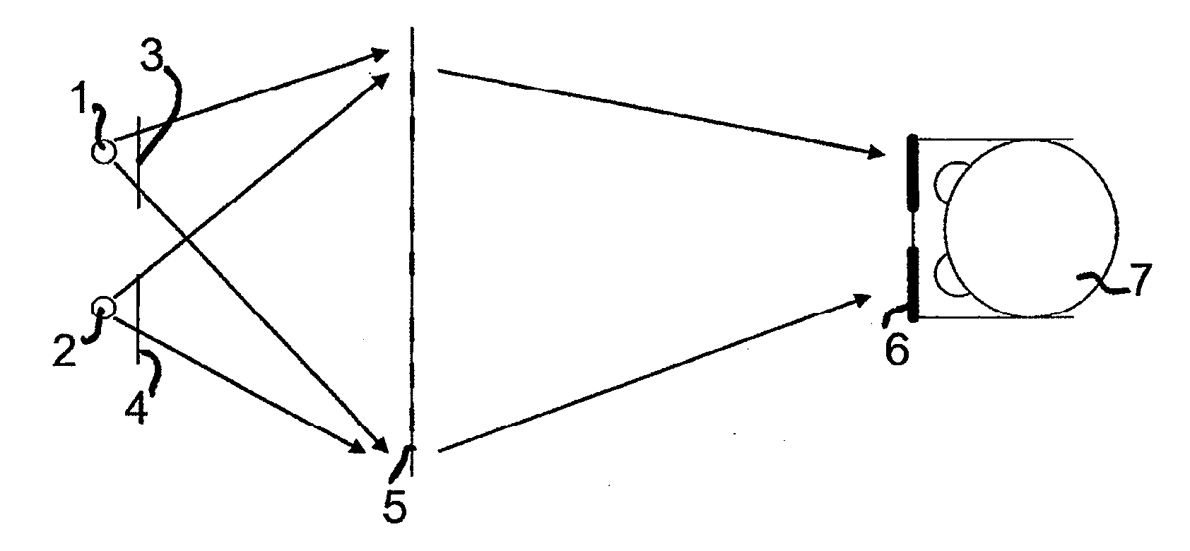
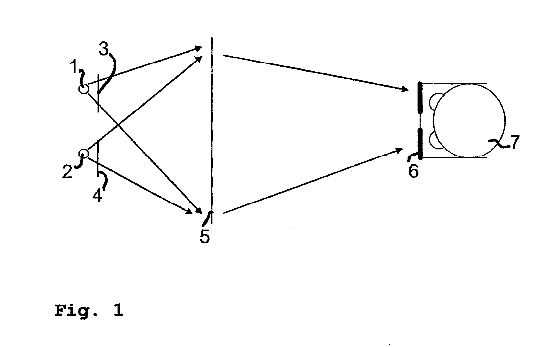
[0048]The present invention enables the reasonably priced use of the wavelength-division multiplexing method with conventional display technologies. An exemplary system of the invention for reproducing stereo images is shown in FIG. 1.

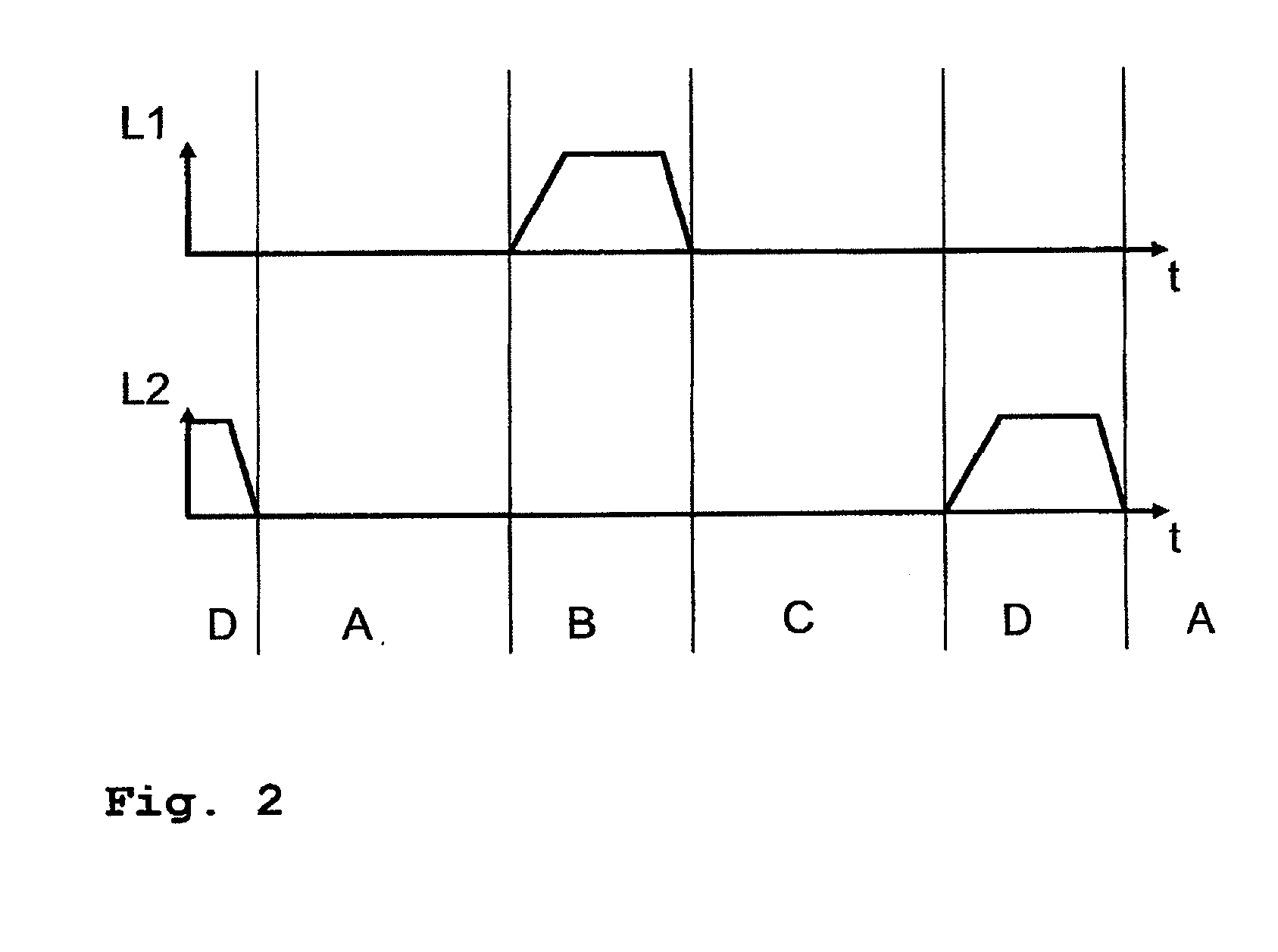
[0049]In this system, two luminous sources 1 and 2 each with different orthogonal spectral properties are switched sequentially in a synchronous manner with two different image contents (right or left image of the stereo image), which are presented on an LCD pixel array 5. The different spectral ranges, orthogonal to one another, of the two luminous sources 1 and 2 are created by filters 3 and 4.

[0050]The image contents and spectral ranges of luminous sources 1 and 2 in this regard are synchronized in time so that a colored image, but individual for each eye, can be provided for both eyes of the viewer 7. The separation of the image contents at the viewer's eye occurs by glasses 6, whose lenses allow the spectral, ranges to pass through for the particu...


PUM


Abstract

A system for reproducing stereographic images is provided that includes a display unit that has a pixel array for representing image data which reproduces the same when controlled with stereoscopic image data, and a light source for fully illuminating the pixel array. The system further includes a pair of glasses that are suitable to make the reproduced stereoscopic image data available to a wearer of the pair of glasses in an eye-selective manner. The display unit has at least one additional light source for fully illuminating the pixel array. Every light source is additionally configured to emit light in a plurality of narrow spectral ranges, thereby defining a color range, the spectral ranges of the light sources being orthogonal to each other. They system also includes a control unit that sequentially operates the light sources. The pair of glasses has optical glasses, spectral transmission ranges of which are orthogonal to each other and correspond to the spectral ranges of the light sources in such a manner as to allow the reproduction of stereographic images in a reliable and cost-effective manner.

Description

[0001]This nonprovisional application is a continuation of International Application No. PCT / DE2008 / 001370, which was filed on Aug. 21, 2008, and which claims priority to German Patent Application No. 20 2007 012 236.5, which was filed in Germany on Aug. 31, 2007, and which are both herein incorporated by reference.BACKGROUND OF THE INVENTION[0002]1. Field of the Invention[0003]The invention relates to a system for the stereoscopic reproduction of images, such as video clips, films, etc.[0004]2. Description of the Background Art[0005]There are various techniques for three-dimensional reproduction. The anaglyph technique has been long known: A stereoscopic impression forms for the viewer by simple red / green superimposition of both left / right partial images and viewing of the total image through filter glasses, which let through only the corresponding color component for a particular eye. A drawback here is the system-related color filtering, so that no realistic color images can be r...

Claims


Application Information

Patent Timeline
IPC IPC(8): G02B27/22
CPCG02B27/2207H04N13/0431G03B35/26G02B30/23H04N13/334H04N13/324
Inventor SIMON, ARNOLDMUELLER, THOMASJORKE, HELMUT
Owner INFITEC
Learn More