Antenna

a technology of antennas and antennas, applied in the direction of resonant antennas, elongated active elements, radiating elements, etc., can solve the problems of low integration, high cost of the currently available antennas for mobile communication terminals, and the further development of the technology of mobile communication terminals

Inactive Publication Date: 2010-06-10
LAIRD TECHNOLOGIES (SHENZHEN) LTD
View PDF4 Cites 28 Cited by
  • Summary
  • Abstract
  • Description
  • Claims
  • Application Information

AI Technical Summary

Benefits of technology

[0015]The objective of the present invention is to increase the frequency width of an antenna inbuilt in a mobile phone, improve the radiation efficiency and the return loss, therefore provide an inbuilt antenna having a bandwidth capable of covering a plurality of wavebands for mobile phones or other mobile communication terminals.
[0016]As the inventor of the present invention found upon research and experimentation, the matching between main antenna and parasitic antenna can be improved by connecting a matching element between conductor strip of the main antenna and conductor strip of the parasitic antenna, so as to improve the coupling of the two, and hence improve the frequency width, the radiation efficiency and the return loss of the antenna.

Problems solved by technology

However, the technology concerning the antenna portion, especially the antenna portion for mobile communication terminals, has been progressing slowly as the performance and structural dimension of the antenna portion are affected by such factors as the structure and size of the mobile communication terminal, the mounting positions of the electronic elements and the material of the housing of the mobile communication terminal, which results in relatively low integration and relatively high cost of the currently available antennas for the mobile communication terminal, and thus restricts further development of the technology of the mobile communication terminal.
Although the shape and size of the antenna can be subjected to various modifications, the operation of the antenna is unexceptionally based on the principle of electromagnetic field radiation.
Seen as such, antenna is an indispensable wireless unit for transmitting and receiving electromagnetic wave, and it is impossible to perform wireless communication without antenna.
Furthermore, the size and shape of the antenna also greatly affect the aesthetic appearance and the production cost of the wireless device.
The disadvantages of the external antenna are that the antenna cannot be integrated to the printed circuit board or the housing of the device, thus the total size of the device is increased (especially of the telescopic type); that the antenna is easily broken or bent; that the antenna specific absorptivity (the SAR value) is high; and that it is difficult to cover a broad range of waveband.
Although the size and volume of such inbuilt antennas can be manufactured to be extremely small, these antennas cannot excellently satisfy the requirements of RF performance and bandwidth.
But these solutions cannot cover all wavebands of GSM850 / GSM900 / DCS / PCS and UMTS, and simultaneously satisfy the requirement of RF performance.
This means that the impedance of the antenna is bad here, which results in a great loss.
At the same time, the return loss curve of the antenna is also relatively shallow in DCS band, which means that not only the loss of the antenna is great in this band, but it also fails to cover from DCS / PCS to UMTS.
However, as shown by the result, the return loss obtained by test in DCS band changes not much.
Seen as such, the introduction of matching element to the transmission line of the circuit board has only limited efficacy.

Method used


Image

  • Antenna
  • Antenna
  • Antenna

Examples


first embodiment

The First Embodiment

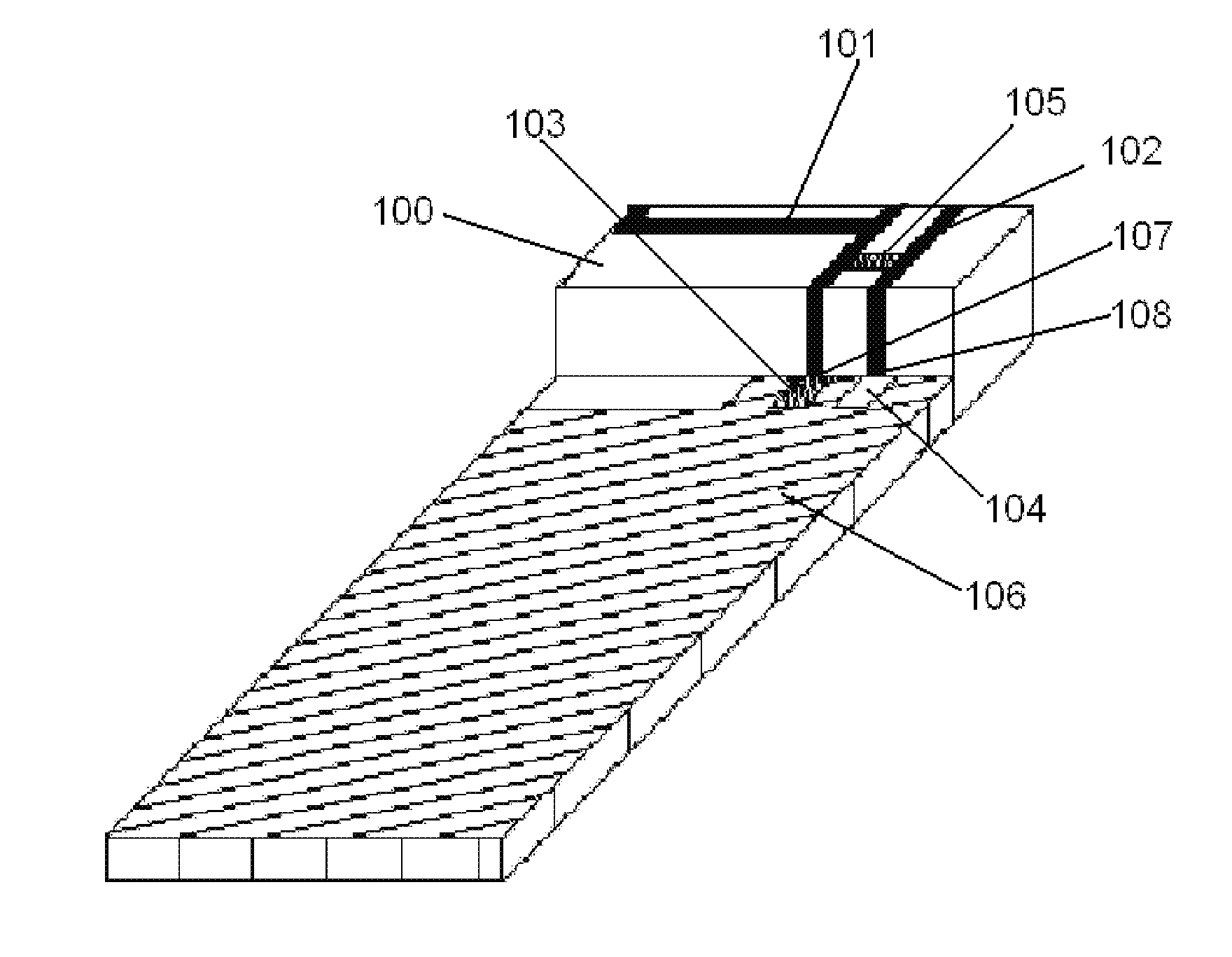
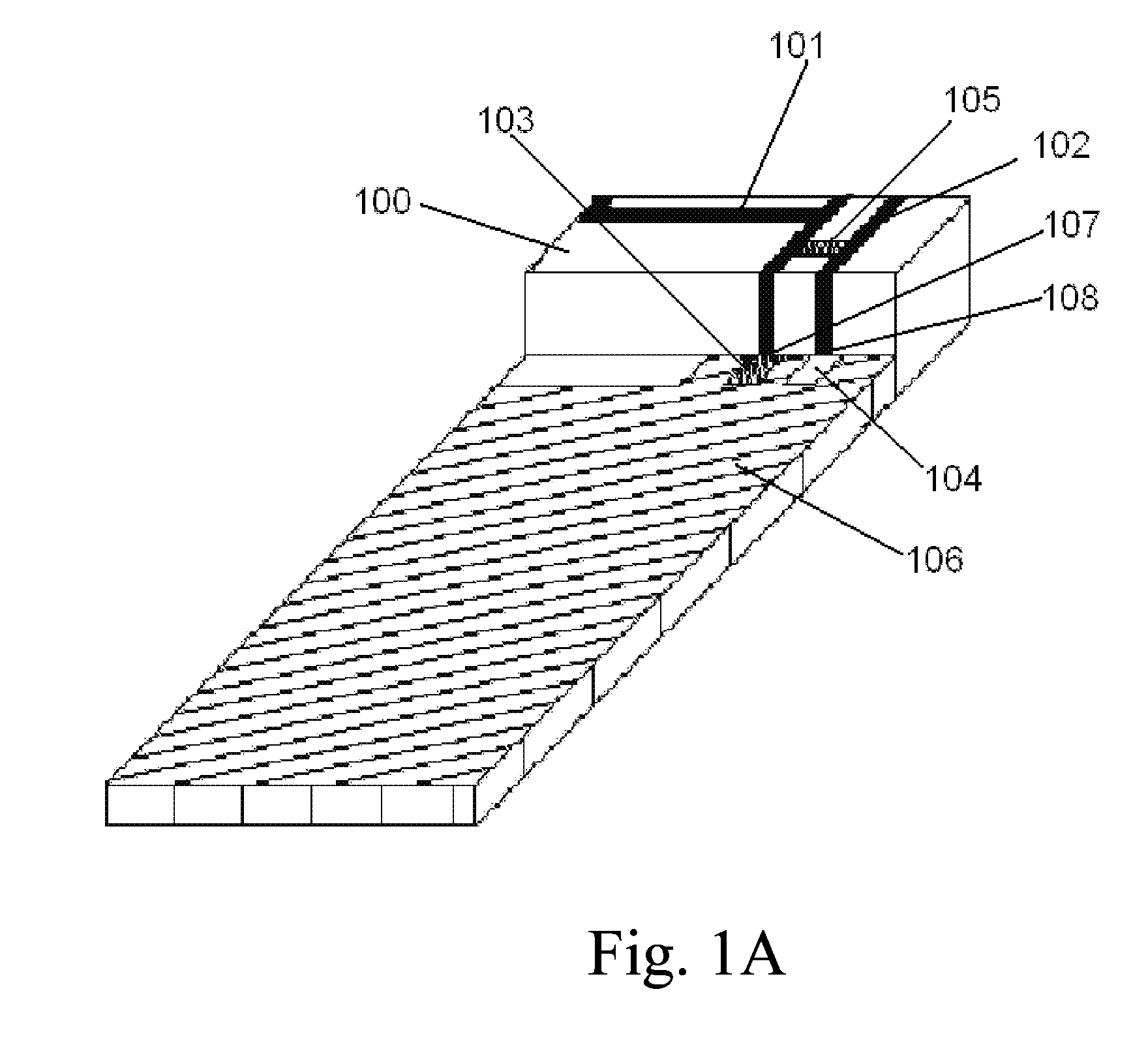
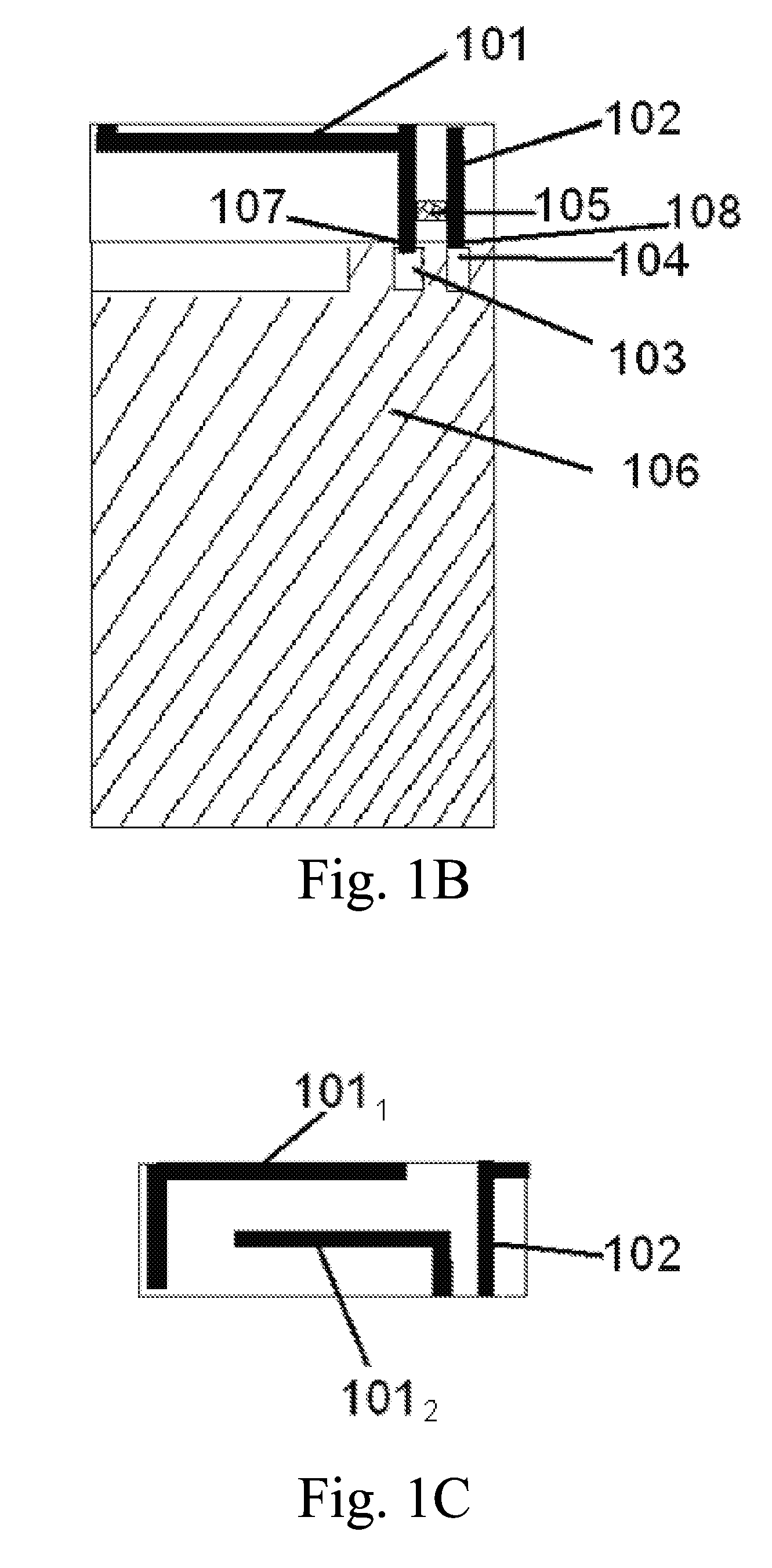
[0036]FIG. 1A is a perspective view showing the antenna according to a first embodiment of the present invention, FIG. 1B is a plan view showing the antenna according to the first embodiment of the present invention, and FIG. 1C is a side view showing the antenna according to the first embodiment of the present invention.

[0037]The antenna of the first embodiment is an inbuilt antenna for mobile phone. The antenna is a five-band antenna. To such an antenna, it is required to cover 5 operation wavebands from GSM / 850 / 900 / DCS / PCS to UMTS, namely cover most wavebands of the current 3 G communications.

[0038]As shown in FIG. 1A, the antenna body 100 is divided into three parts: a main antenna 101, a parasitic antenna 102 and a matching element 105. The main antenna 101 and the parasitic antenna 102 constitute an antenna unit. The antenna unit can be formed by flexfilm technology, and forms an opened rectangular ring. A base (not shown) made of insulating material such a...

second embodiment

The Second Embodiment

[0056]The antenna according to the second embodiment of the present invention will be described in detail. In the following description, parts that are same to the first embodiments are not described in detail, as emphasis is put only on the different points.

[0057]FIGS. 2A and 2B show the antenna structure according to the second embodiment of the present invention, of which FIG. 2A is a plan view showing the antenna according to the second embodiment of the present invention, and FIG. 2B is a side view showing the antenna according to the second embodiment.

[0058]The antenna according to the second embodiment comprises a circuit board 206, a main antenna 201, a parasitic antenna 202, and an inductor 205 as a matching element, the inductor 205 is connected to conductor strips of the main antenna 201 and the parasitic antenna 202. In this embodiment, the main antenna 201 is disposed on a conductor strip of the circuit board, and has branches 2011 and 2012 like the...

third embodiment

The Third Embodiment

[0060]The antenna according to the third embodiment of the present invention will be described in detail. In the following description, parts that are same to the first embodiments are not described in detail, as emphasis is put only on the different points.

[0061]FIGS. 3A and 3B show the antenna structure according to the third embodiment of the present invention, of which FIG. 3A is a plan view showing the antenna according to the third embodiment of the present invention, and FIG. 3B is a side view showing the antenna according to the third embodiment.

[0062]Like the first embodiment, the antenna according to the third embodiment comprises a main antenna 301, a parasitic antenna 302 and an inductor element 305 as a matching element, the inductor element 305 is connected between the main antenna 301 and the parasitic antenna 302. Different from the first embodiment, in the third embodiment the main antenna 301 has a feed foot 309 and a grounding foot 308, and a f...


PUM


Abstract

The invention provides an antenna for wireless devices which improves matching of the main antenna element and parasitic antenna element in the antenna. The antenna of the invention comprises a main antenna element and a parasitic antenna element, the main antenna element and the parasitic antenna element being separated from each other, a matching element is connected between the main antenna element and the parasitic antenna element, with an end of the matching element being electrically connected to a conductor strip of the main antenna element, and the other end being electrically connected to a conductor strip of the parasitic antenna element. Optimized antenna performance can be achieved by adjusting position and value of the matching element.

Description

TECHNICAL FIELD[0001]The present invention relates to an antenna for mobile communication terminals, and more particularly to an inbuilt antenna capable of covering a plurality of wavebands for mobile phones or other mobile communication terminals.DESCRIPTION OF THE RELATED ART[0002]With the rapid development of the mobile communications technology and the wide application of mobile wireless system, the mobile phone as a terminal of the mobile communications system is developing toward miniaturization, multi-mode (with simultaneous compatibility of GSM850 / GSM900 / DCS / PCS / UMTS) and high performance.[0003]On the side of manufacturers of mobile communications terminals, the radio frequency (RF) circuit portion, the baseband portion and the digital signal-processing portion have by now achieved high-level integration, which effectively promoted the miniaturization and low production cost of the mobile communications terminal devices. However, the technology concerning the antenna portion...

Claims


Application Information

Patent Timeline
Patent Type & Authority Applications(United States)
IPC IPC(8): H01Q5/00H01Q1/24H01Q1/38H01Q5/371H01Q5/392
CPCH01Q1/243H01Q1/38H01Q5/392H01Q5/371H01Q9/42H01Q1/24H01Q9/04
Inventor ZHANG, LIXIAGUO, XIAOJUAN
Owner LAIRD TECHNOLOGIES (SHENZHEN) LTD
Why Eureka
Try Eureka