Method of transmitting sounding reference signal in wireless communication system
a wireless communication and reference signal technology, applied in the field of wireless communication, can solve problems such as difficulties in improving spectral efficiency, and achieve the effects of reducing the overhead of scheduling the transmission of the reference signal, reducing the battery consumption of the user equipment, and improving spectral efficiency
- Summary
- Abstract
- Description
- Claims
- Application Information
AI Technical Summary
Benefits of technology
Problems solved by technology
Method used
Image
Examples
first embodiment
Operation of Two-Types of Pucchs
[0105]Two types of PUCCHs are defined according to coexistence with an SRS in one subframe. For example, a type-1 control channel (or a symmetric control channel) cannot coexist with the SRS, and a type-2 control channel (or an asymmetric control channel) can coexist with the SRS.
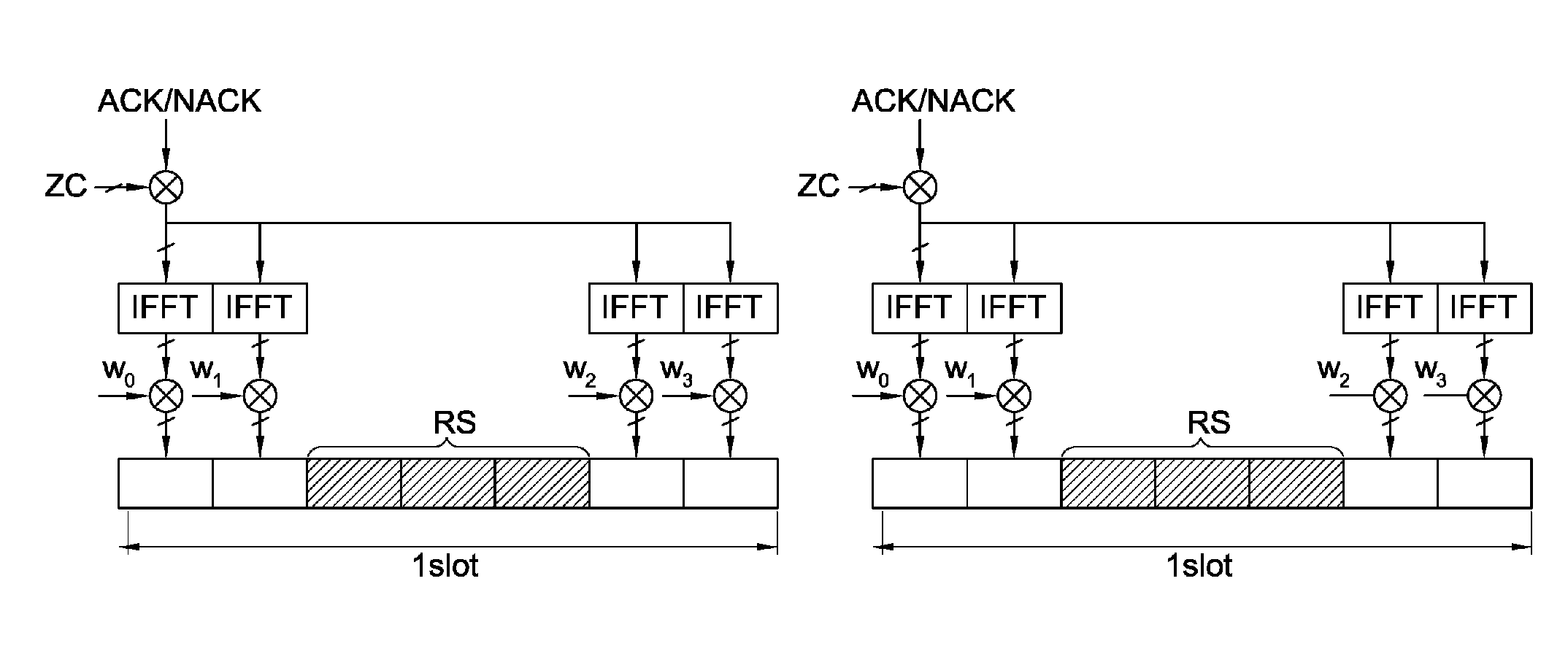
[0106]FIG. 12 shows an example of the two-types of PUCCHs. The type-1 control channel is a general PUCCH which is used for an ACK / NACK channel when it is not necessary to simultaneously transmit an ACK / NACK signal and the SRS in at least one resource block of an arbitrary subframe. During the subframe in which the type-1 control channel is used, another UE can transmit the SRS by using the resource block. The type-2 control channel is an optional PUCCH provided in consideration of the transmission of the SRS. A first slot includes an SC-FDMA symbol that is punctured to transmit the SRS. A spreading factor (SF) of a region for transmitting the ACK / NACK signal is 3 in the first...
second embodiment
Scheduling Performed by BS
[0120]A BS performs scheduling so that UEs do not simultaneously transmit uplink control information and an SRS.
[0121]FIG. 20 shows an example of a scheduling method performed by a BS. If a UE1 intends to transmit an SRS in a specific subframe, the BS prevents the UE1 from transmitting an ACK / NACK signal on a PUCCH in the subframe. Instead, the BS schedules so that another UE other than the UE1 transmits the ACK / NACK signal in the subframe. That is, the BS schedules so that one UE cannot simultaneously transmit the SRS in one subframe and uplink control information on a PUCCH. This can be achieved by using additional signaling or by transmitting a predetermined SRS.
[0122]On the contrary, if there is no need to limit the downlink transmission for the UE1, the BS can prevent the SRS from being transmitted in the subframe.
third embodiment
Operation of Single-Type PUCCH
[0123]A PUCCH in use can be designed so that uplink control information and an SRS are not transmitted through the same resource region. The PUCCH has the same structure irrespective of whether the SRS is transmitted or not. That is, irrespective of whether the SRS is transmitted or not, the PUCCH has a structure in which the SRS is transmitted through only a specific resource region and the control signal is transmitted through only the remaining resource regions other than the specific resource region under the assumption that the specific resource region (e.g., SC-FDMA symbol(s)) designated only for SRS transmission is always used when the SRS is transmitted.
[0124]For this, the aforementioned asymmetric control channel structure can be used as a fixed PUCCH structure. For example, in the ACK / NACK channel, a first slot uses 3 demodulation reference signal symbols and 3 ACK / NACK symbols, and the remaining one symbol is punctured to be dedicated for the...
PUM
 Abstract
Description
Claims
Application Information
 - R&D
- Intellectual Property
- Life Sciences
- Materials
- Tech Scout
- Unparalleled Data Quality
- Higher Quality Content
- 60% Fewer Hallucinations
Browse by: Latest US Patents, China's latest patents, Technical Efficacy Thesaurus, Application Domain, Technology Topic, Popular Technical Reports.
© 2025 PatSnap. All rights reserved.Legal|Privacy policy|Modern Slavery Act Transparency Statement|Sitemap|About US| Contact US: help@patsnap.com


