Acoustic sensor element
- Summary
- Abstract
- Description
- Claims
- Application Information
AI Technical Summary
Benefits of technology
Problems solved by technology
Method used
Image
Examples
Embodiment Construction
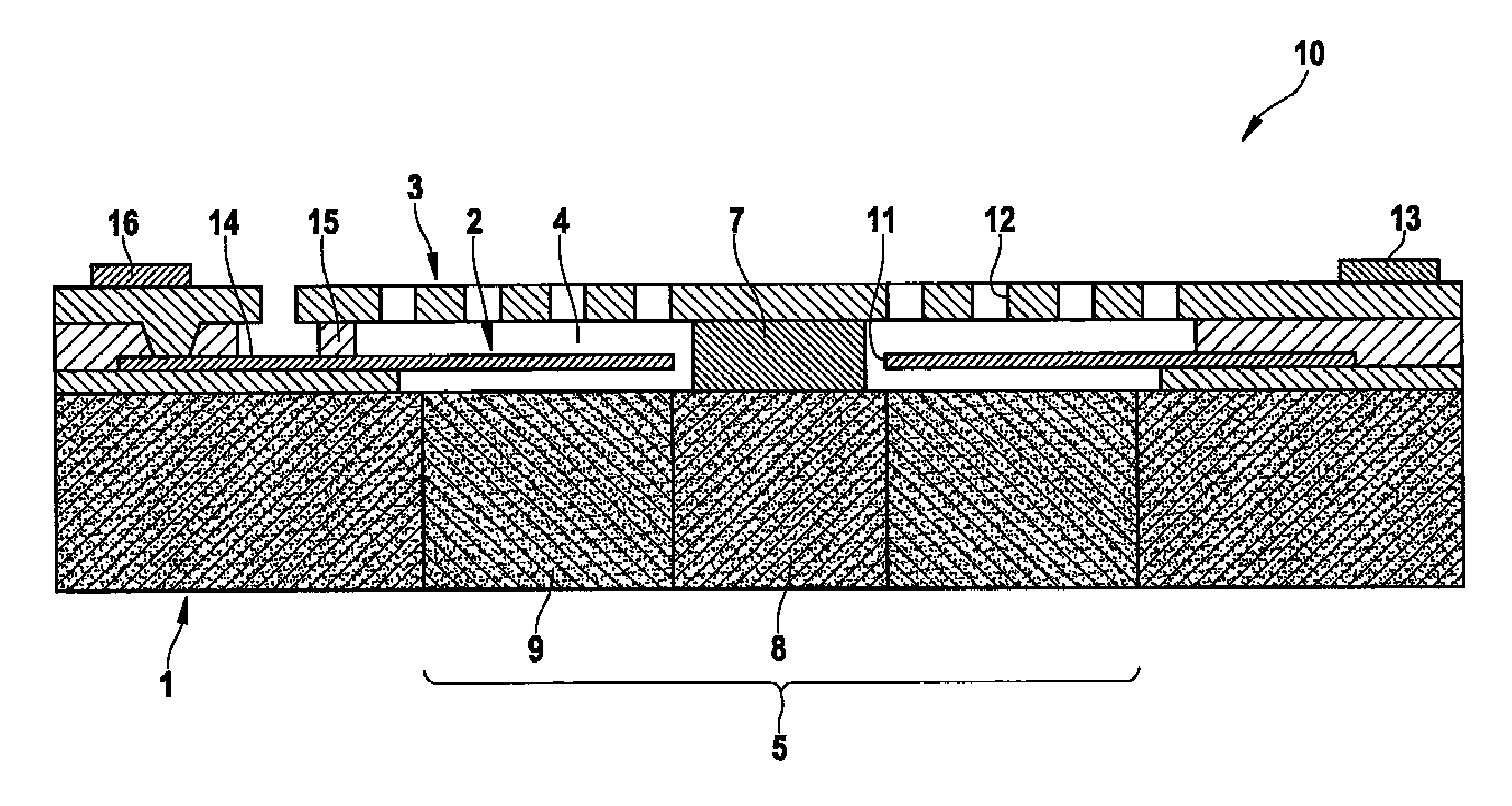
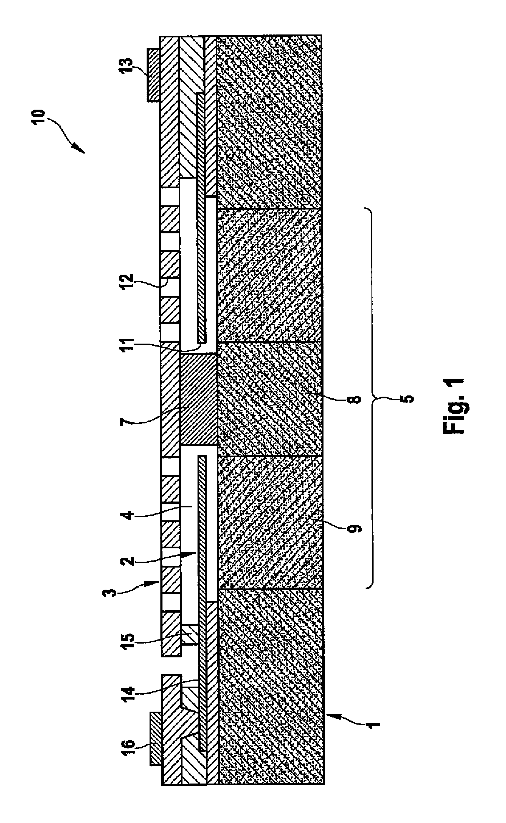
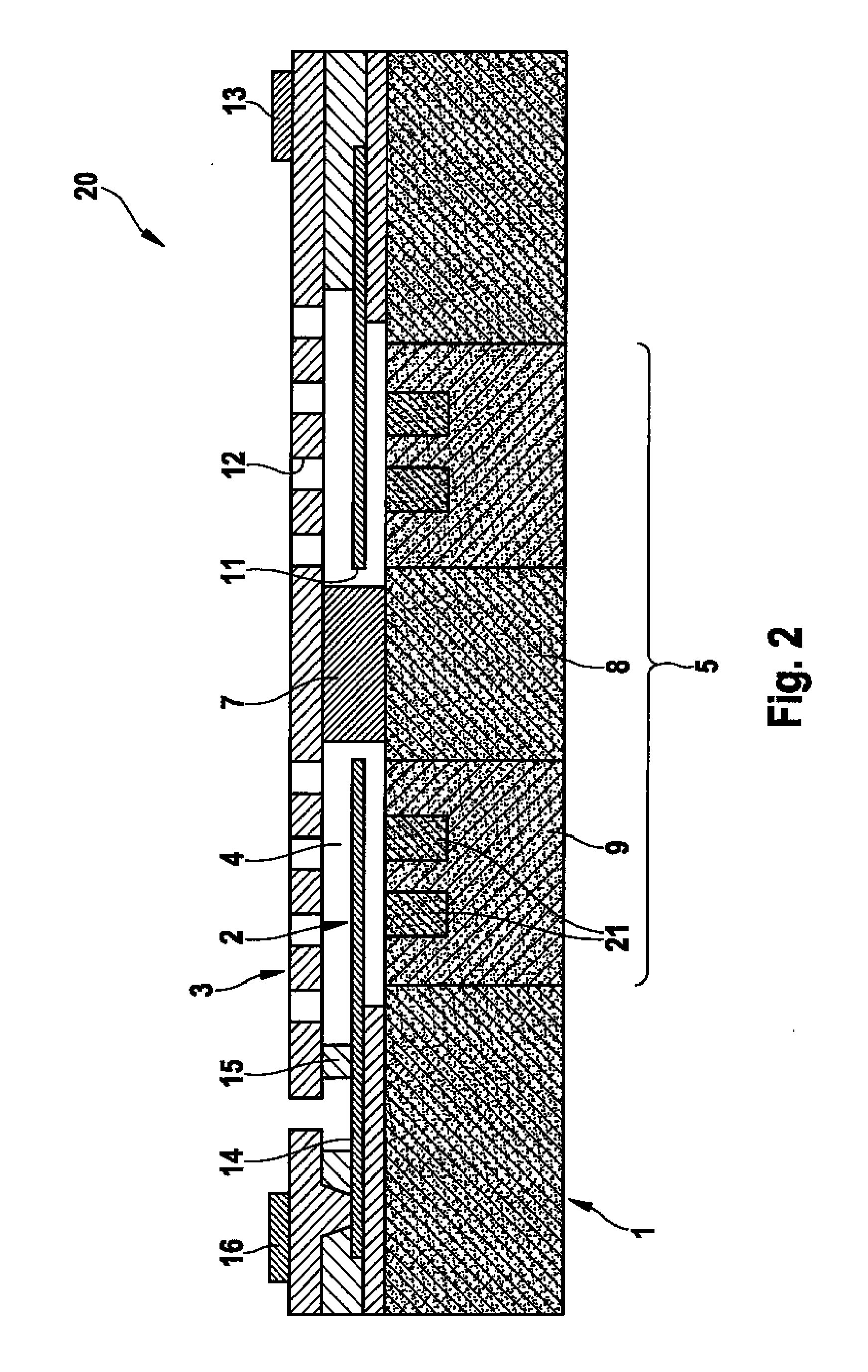
[0021]The layer structure of acoustic sensor element 10 shown in
[0022]FIG. 1 includes a substrate 1 above which a diaphragm 2 and a fixed counter element 3 are developed. Diaphragm 2 is situated in a cavity 4 between substrate 1 and counter element 3 and acts as movable electrode of a capacitor system, while counter element 3 forms a fixed counter electrode of this capacitor system. Substrate 1 is structured in region 5 underneath cavity 4. Here there are through-holes for the application of sound waves to diaphragm 2, as illustrated in FIG. 3a. Counter element 3 is connected to substrate 1 via a support element 7. Support element 7 is situated in the region of cavity 4 and sits on a substrate base 8, which is part of the substrate structure underneath cavity 4. In addition, this substrate structure includes webs 9, via which substrate base 8 is connected to “substrate mainland”1 in the edge region of cavity 4. Substrate base 8 as well as webs 9 are realized in the full thickness of...
PUM
 Abstract
Description
Claims
Application Information
 - Generate Ideas
- Intellectual Property
- Life Sciences
- Materials
- Tech Scout
- Unparalleled Data Quality
- Higher Quality Content
- 60% Fewer Hallucinations
Browse by: Latest US Patents, China's latest patents, Technical Efficacy Thesaurus, Application Domain, Technology Topic, Popular Technical Reports.
© 2025 PatSnap. All rights reserved.Legal|Privacy policy|Modern Slavery Act Transparency Statement|Sitemap|About US| Contact US: help@patsnap.com


