
Light emitting device and lighting device having the same

a technology of light emitting device and lighting device, which is applied in the direction of lighting and heating apparatus, instruments, lenses, etc., can solve the problem of becoming harder to obtain the higher scattering ability, and achieve the effect of preventing uneven brightness

Active Publication Date: 2010-06-03
ENPLAS CORP
View PDF10 Cites 41 Cited by
  • Summary
  • Abstract
  • Description
  • Claims
  • Application Information

AI Technical Summary

Benefits of technology

[0016]In order to improve the scattering ability of the light flux controlling member 102, it is necessary that the light emitted from the light-emitting elements 101 reach a position away from an area directly above the light-emitting elements 101, on the liquid crystal display panel 106. In order to obtain such light, it is necessary to refract the outgoing light as parallel to the liquid crystal display panel 106 as possible, on the light-outgoing surface 102b. That is, it is necessary to significantly refract the light, on the light-outgoing surface 102b. However, significant light refraction by the light-outgoing surface 102b generally increases a reflex amount, due to a phenomenon called the Fresnel's reflection. That is, an amount of the light emitted from the light-outgoing surface 102b decreases. In particular, the Fresnel's reflection effect becomes significant in the light-emitting device 100 of the Patent Literature 1 since the light-emitting device 100 is arranged such that control of the light direction is mainly performed only at the light-outgoing surface 102b, thereby having a need for significantly refracting the light on the light-outgoing surface 102b so that the higher scattering ability is obtained.
[0023]The present invention is made in view of the problem, and an object of the invention is to realize a light-emitting device that (i) scatters light without generating uneven brightness on a liquid crystal display panel and (ii) has higher scattering ability that is obtained by decreasing a reflectance caused by the Fresnel's reflection.
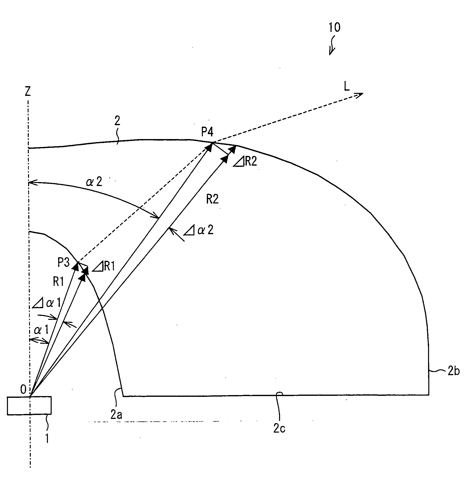
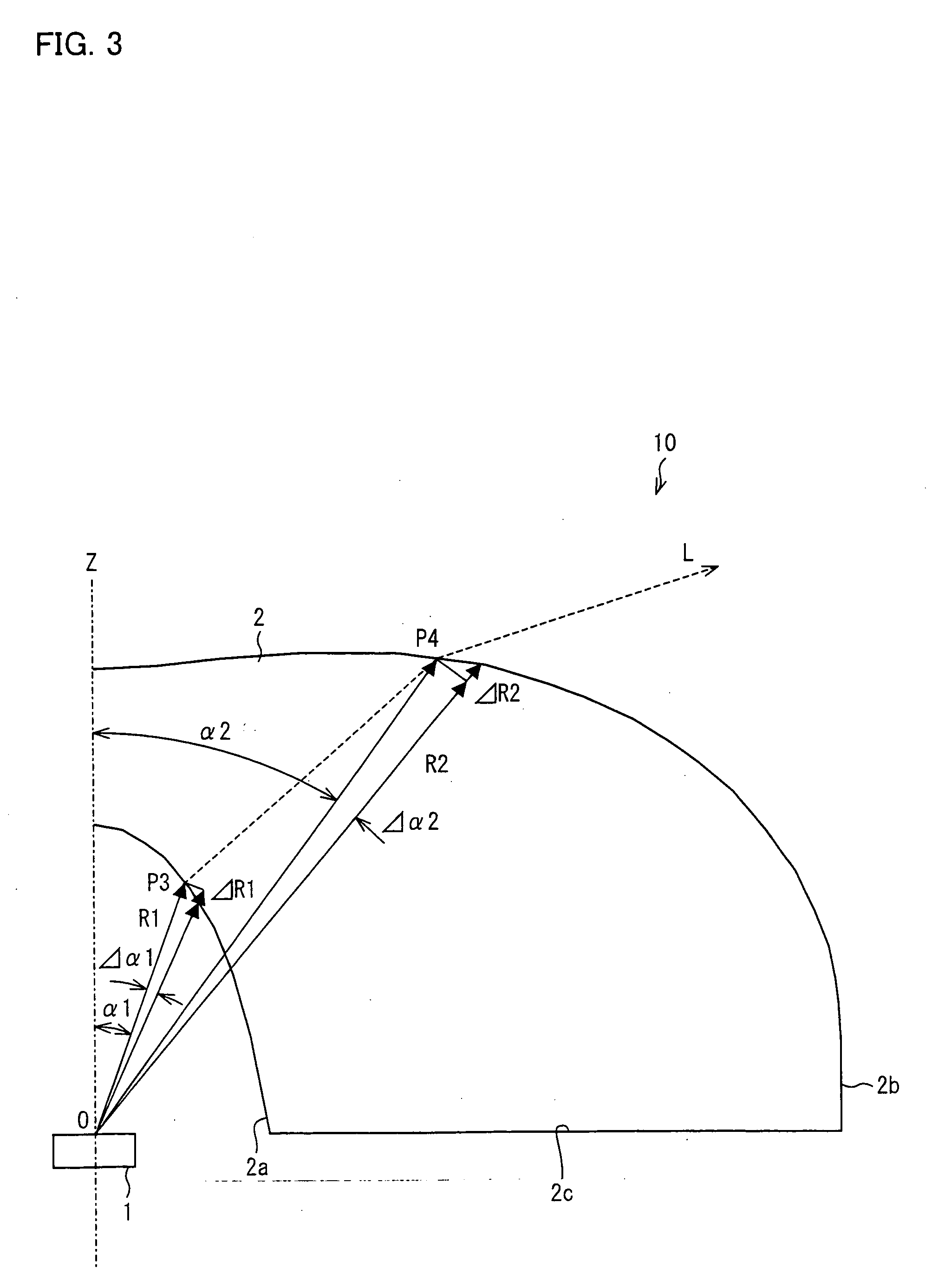
[0025]In a light-emitting device that satisfies the above equations (1) and (2), it is possible to make distribution of light emitted from the light-emitting element close to the Gaussian distribution, on a plane that is provided at a certain distance in a direction parallel to the reference light axis so as to be perpendicular to the reference light axis, e.g. on a liquid crystal display panel. Thus, it is possible to prevent the uneven brightness caused by the light on the plane.

Problems solved by technology

However, the aforesaid conventional lighting devices cause the following problems, respectively.
As such, it becomes harder to obtain the higher scattering ability.

Method used


Image

  • Light emitting device and lighting device having the same
  • Light emitting device and lighting device having the same
  • Light emitting device and lighting device having the same

Examples


embodiment 1

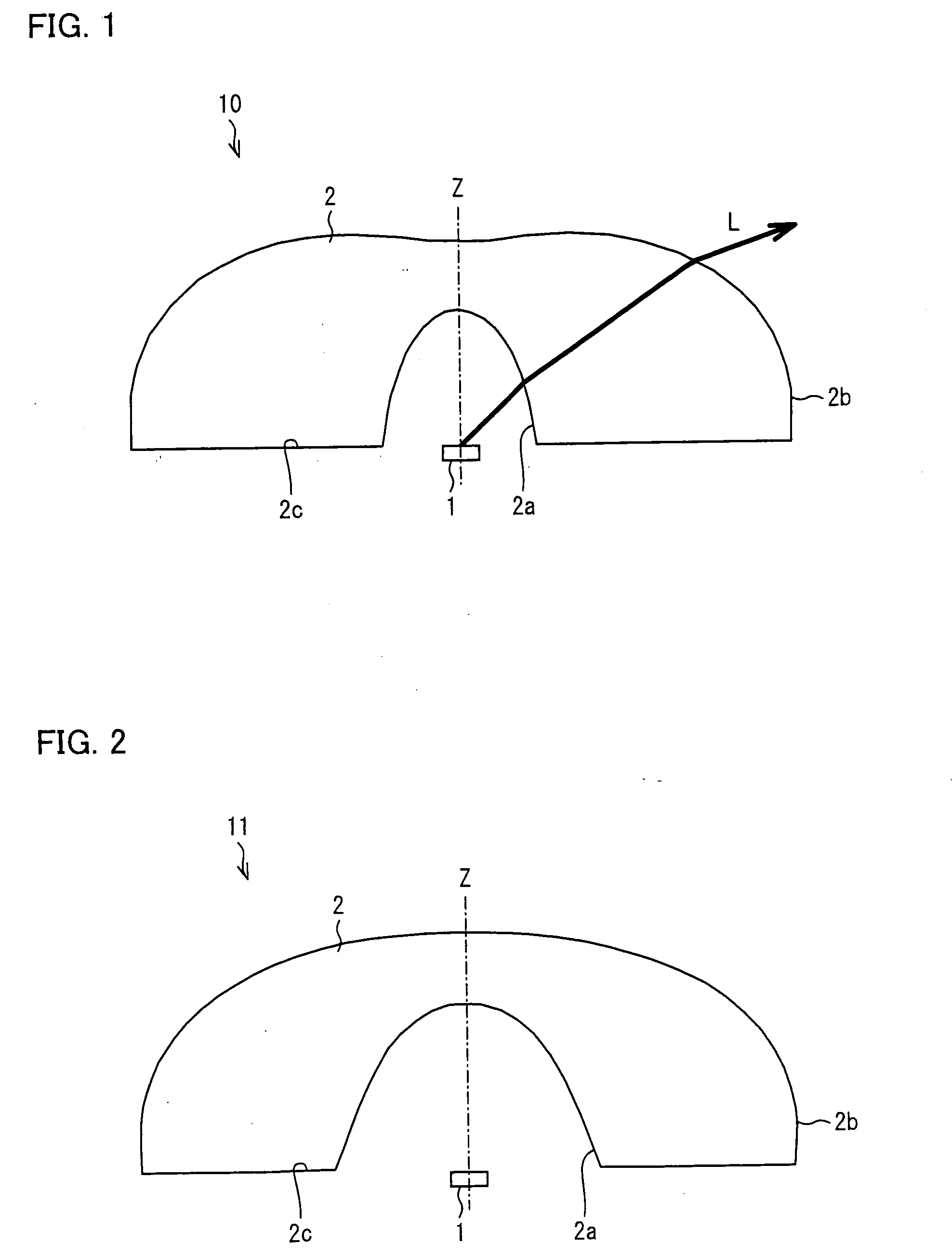
[0048]One embodiment of the present invention is described below with reference to FIGS. 1 through 9. FIG. 1 is a cross-sectional view illustrating a light-emitting device 10 in accordance with the present embodiment. The light-emitting device 10 illustrated in FIG. 1 includes a light-emitting element 1 and a light flux controlling member 2 arranged to surround and cover the light-emitting element 1. A direction of a light axis Z (a reference light axis) indicates a direction in which light proceeds three-dimensionally at a center of an outgoing light flux of light that is emitted from the light-emitting element 1. For convenience, in FIG. 1, a direction vertical to the light-emitting element 1 is set as the light axis (the reference light axis) Z.

[0049]Furthermore, the light-emitting device 10 has a rotation-symmetrical shape with respect to the light axis Z. However, the light-emitting element 1 does not necessarily have a rotation-symmetrical shape. Alternatively, the light-emitt...

embodiment 2

[0081]The following describes another embodiment in accordance with the present invention, with reference to FIGS. 10 through 12. An arrangement other than described in the present embodiment is the same as that described in Embodiment 1. For an easy explanation, members having the same functions as those shown in figures in Embodiment 1 are given the same reference numerals, and explanations thereof are omitted.

[0082]FIG. 10 is a cross-sectional view of a light-emitting device 10 in accordance with the present embodiment. In the light-emitting device illustrated in FIG. 10, a light-emitting element 1 and a light flux controlling member 2 are provided with a certain distance therebetween. In such an arrangement, a part of light emitted from a light-emitting element 1 may directly enter a bottom surface 2c, without entering a light-incoming surface 2a. Subsequently, the light is transmitted through the light flux controlling member 2; is condensed on a light-outgoing surface 2b; and,...

embodiment 3

[0090]The following describes yet another embodiment in accordance with the present invention, with reference to FIGS. 13 through 18. Arrangements other than described in the present embodiment are the same as those described in Embodiment 1. For convenience, members having the same functions as those shown in the figures in Embodiment 1 are given the same reference numerals, and explanations thereof are omitted.

[0091]FIG. 13 is a cross-sectional view of a light-emitting device 14 in accordance with the present embodiment. The light-emitting device 14 includes a light scattering section 5 of a cuneal shape on a bottom surface 2c. The light scattering section 5 is not limited to a particular kind, provided that the light scattering section 5 (i) reflects light in a same manner as a bezel of a prism having a cuneal shape or the like and (ii) deflects a light direction almost perpendicular to the light axis Z. In FIG. 13, the light scattering section 5 has a rotationally symmetrical sh...


PUM


Abstract

A light-emitting device (10) includes: a light-emitting element (1); and a light flux controlling member (2) for controlling light emitted from the light-emitting element (1), the light flux controlling member (2) has (i) a light-incoming surface (2a) which the light emitted from the light-emitting element (1) enters and (ii) a light-outgoing surface (2b), and the following equation (1) is satisfied where r is a length, from a light axis Z of the light-emitting device (10), of a plane that is provided at a certain distance from the light flux controlling member (2) in a direction parallel to the light axis Z so as to be perpendicular to the light axis Z, φ1 is an angle between the light emitted from the light-emitting element (1) and the light axis, P(φ1) is a light distribution property of the light-emitting element (1). This provides a light-emitting device that scatters light without generating uneven brightness on a liquid crystal display panel, reduces a reflectance caused by the Fresnel's reflection, and has an improved scattering ability.

Description

TECHNICAL FIELD[0001]The present invention relates to a light-emitting device and a lighting device having the same, and more particularly, relates to: a light-emitting device (i) having a light flux controlling member and a lighting device having this light-emitting device, which are capable of being used as, for example, a light source for use in a backlight that performs planar irradiation to a liquid crystal display panel from a back surface side of the liquid crystal display panel and an ordinal interior lighting.BACKGROUND ART[0002]Conventionally, it has been known to use a surface light source device using plural light-emitting diodes (hereafter, referred to as “LED,” as appropriate) as lighting means for irradiating a liquid crystal display monitor for use in a personal computer, a television, and the like. The surface light source device has the plural light-emitting diodes provided in a matrix manner in a tabular region having substantially the same shape as a liquid cryst...

Claims


Application Information

Patent Timeline
Patent Type & Authority Applications(United States)
IPC IPC(8): F21V5/00F21S2/00F21V5/04F21Y101/02G02B5/00G02B5/02H01L33/00H01L33/54H01L33/56
CPCG02B3/02H01L33/60H01L33/58G02B3/04
Inventor KOKUBO, FUMIO
Owner ENPLAS CORP
Learn More