Optical system

Active Publication Date: 2010-06-03
CARL ZEISS SMT GMBH
View PDF21 Cites 4 Cited by
  • Summary
  • Abstract
  • Description
  • Claims
  • Application Information

AI Technical Summary

Benefits of technology

[0010]Considerations have shown that a sufficient correction of the spherical aberration and the Gaussian error may be achieved by the above-mentioned optical system. In addition, the optical system may have a fixed overall length. In particular, the first lens unit may have a telephoto effect, which results in a shortened overall length of the optical system relative to the maximum focal length of the optical system. In addition, only lenses of the first lens unit may be implemented having the free diameter as large as the entry pupil diameter of the optical system. All other lenses may have a free diameter which is significantly smaller. Furthermore, it is possible that through a suitable selection of the focal lengths of the individual lens units, the maximum focal length of the optical system may be implemented substantially solely by the first lens unit. The second lens unit and the third lens unit may form a zoom system downstream from the first lens unit for reducing the focal length. Through this construction, a reduction of the secondary spectrum is made possible, in particular at the maximum focal length of the optical system. This construction may also have a favorable effect on the overall length of the optical system. Furthermore, considerations have shown that the relative aperture of the optical system at a maximum focal length may be at least 1:5.9.
[0028]In an embodiment of the telescope according to the system described herein, the telescope may have an image acquisition unit in the form of a surface sensor, such as a CCD and / or a CMOS sensor. Alternatively thereto, an image acquisition unit may be provided in the form of an ocular, using which an image of an object is imaged on the retina of an observer. In a further embodiment, for example, both a surface sensor and also an ocular may be provided. A telescope according to this embodiment may allow for both observation of the object (retina) and also imaging of the object on a surface sensor simultaneously.

Problems solved by technology

In particular, the first lens unit may have a telephoto effect, which results in a shortened overall length of the optical system relative to the maximum focal length of the optical system.

Method used


Image

  • Optical system
  • Optical system
  • Optical system

Examples


Embodiment Construction

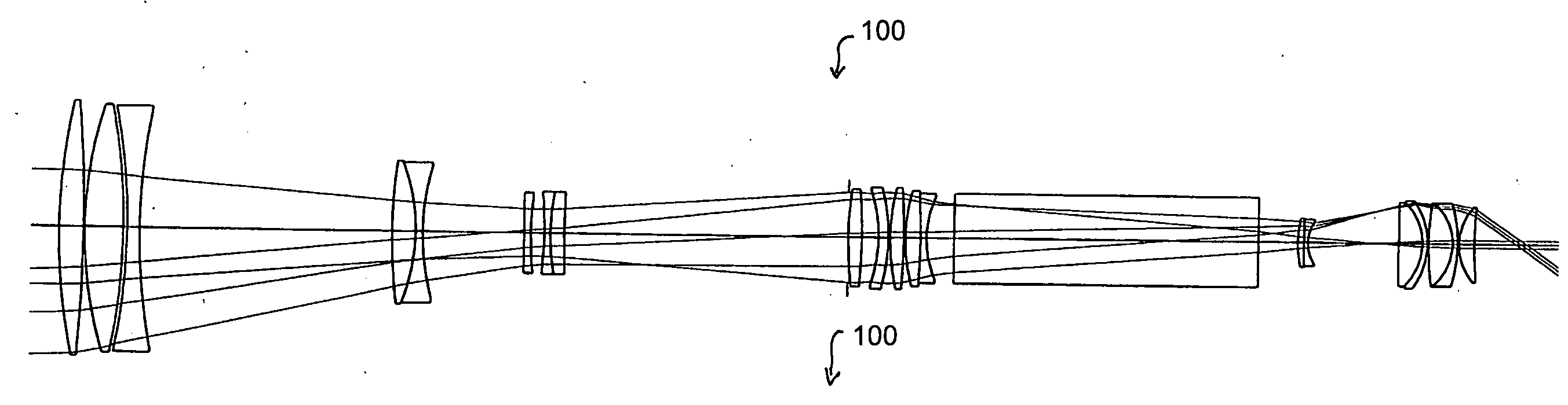
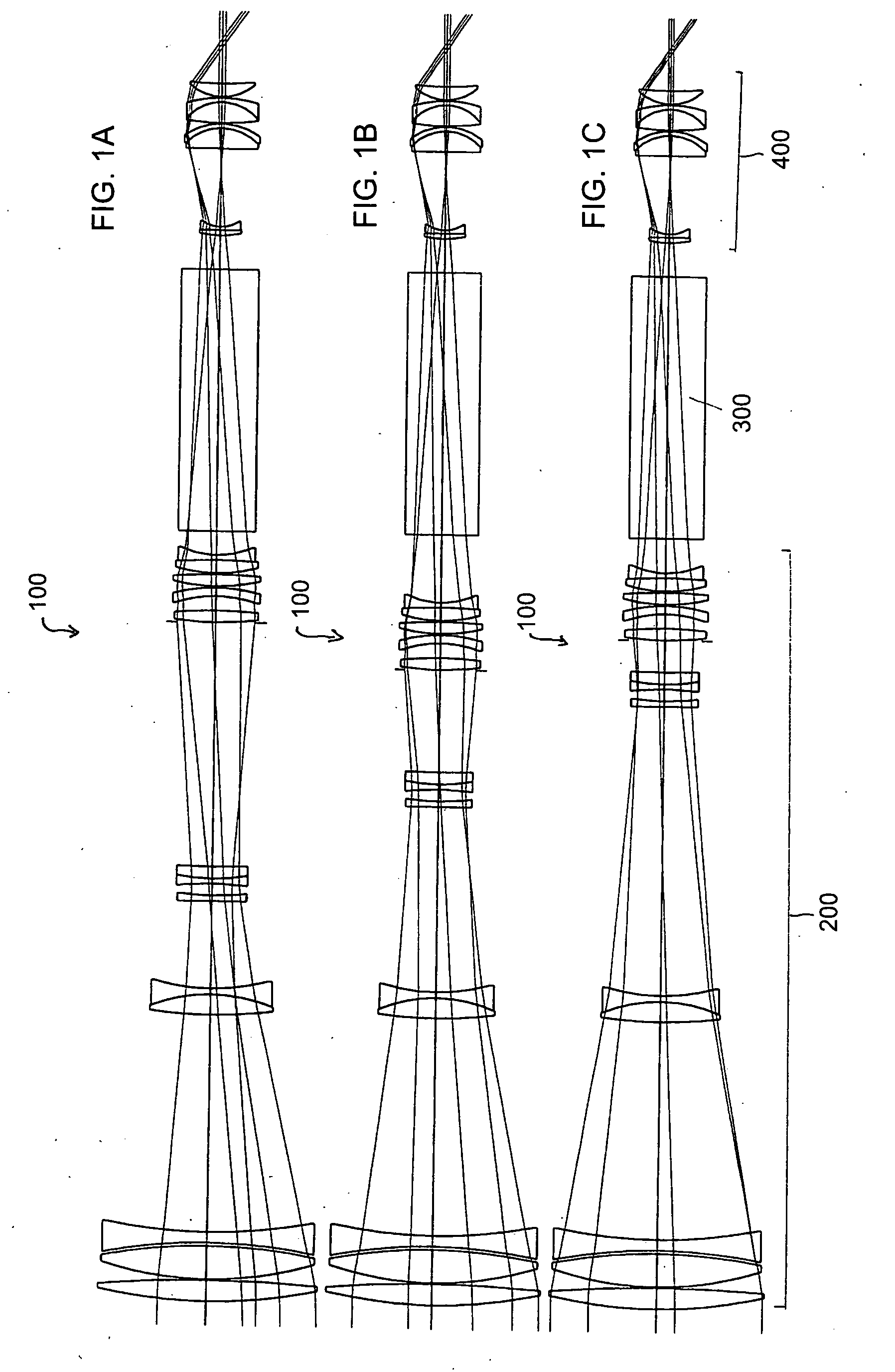
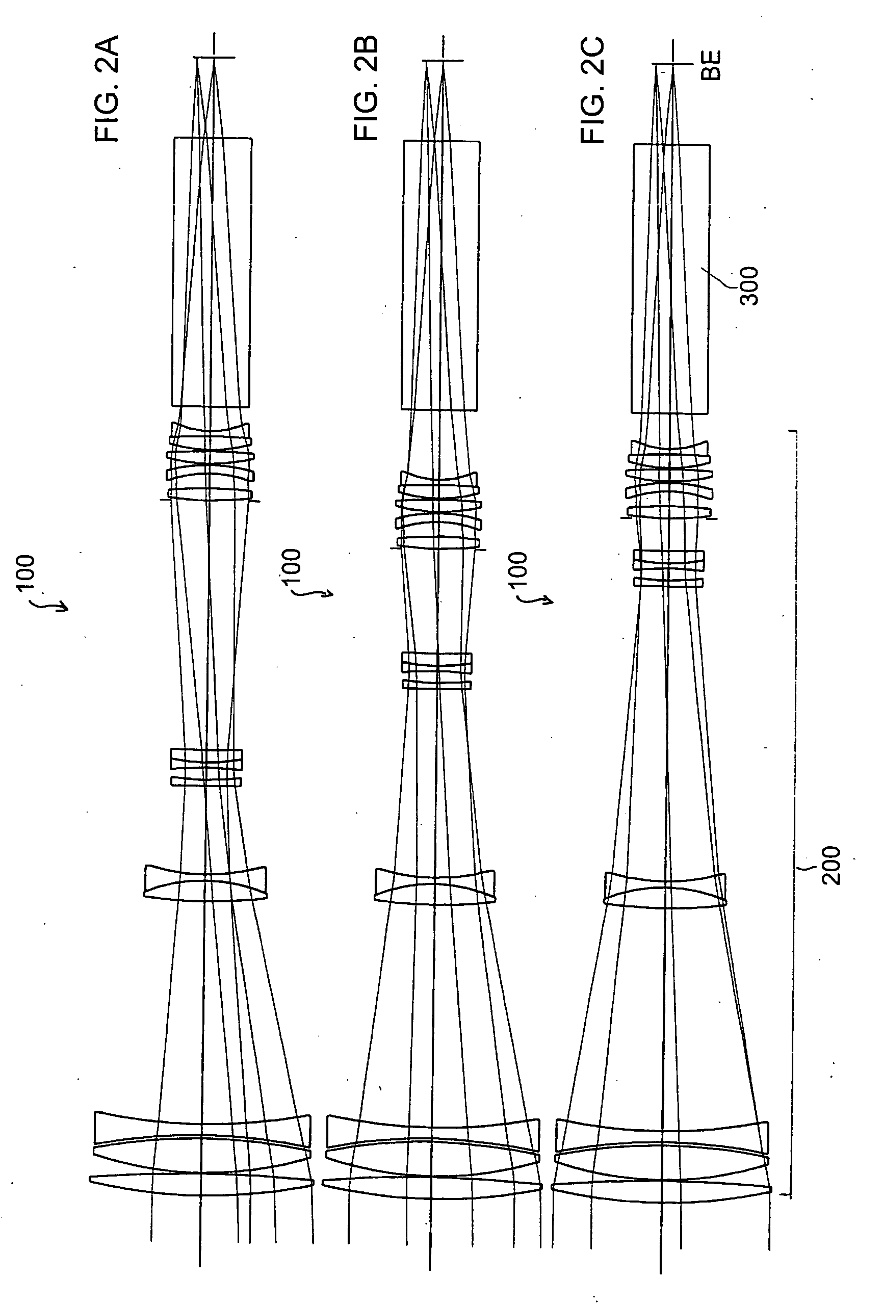
[0037]FIGS. 1A through 1C show a schematic illustration of a embodiment of a telescope 100 according to the system described herein. The telescope 100 may include an optical system in the form of an objective 200, a prism reversal system 300, and an ocular 400. The prism reversal system 300 may additionally be implemented as a beam splitter for dividing incident beams into two partial beam paths. FIGS. 1A through 1C show various settings of the individual optical units of the telescope 100, i.e., the objective 200, in which various magnifications may be achieved. This is discussed in greater detail below.

[0038]The objective 200 may have a variable focal length. For example, the objective 200 may be designed for a focal length range from approximately 166.7 mm to approximately 500 mm. For example, if the ocular 400 having a focal length of approximately 11.1 mm is selected, the telescope 100 will have a variable magnification from approximately 15× to approximately 45×. However, if o...


PUM


Abstract

An optical system for imaging an object on an image acquisition unit has a variable focal length for zooming. The optical system has precisely three lens units from the object in the direction of an image acquisition unit, namely a first lens unit, a second lens unit, and a third lens unit. The second lens unit and the third lens unit are movably situated along an optical axis of the optical system for a change of the focal length. The first lens unit includes a first lens group and a second lens group. The first lens group of the first lens unit is fixedly situated on the optical axis of the optical system. The second lens group of the first lens unit is movably situated along the optical axis of the optical system for focusing. The second lens group includes at least two lenses.

Description

TECHNICAL FIELD[0001]This application relates to an optical system for imaging an object on an image acquisition unit, in particular, an optical system having a variable focal length for zooming.BACKGROUND OF THE INVENTION[0002]A telescope having a variable magnification is known from DE 704 17 03, which is incorporated herein by reference. The telescope has an optical system in the form of a zoom objective, a prism reversal system, and an ocular. The zoom objective is provided with four lens units, namely a first lens unit, a second lens unit, a third lens unit, and a fourth lens unit. In other words, the zoom objective is a four-number system. Two of the above-mentioned lens units, namely the second lens unit and the third lens unit, are situated so they are movable along the optical axis. In contrast, the first lens unit and the fourth lens unit are situated fixed on the optical axis. The fourth lens unit is used for implementing the main portion of the required refractive power ...

Claims


Application Information

Patent Timeline
IPC IPC(8): G02B23/02G02B15/14G02B23/00H04N5/335
CPCG02B23/00G02B15/173G02B15/143105
Inventor TAUTZ, VOLKER
Owner CARL ZEISS SMT GMBH
Why Eureka
Try Eureka