
Method for the Enhancement of Dynamic Underbalanced Systems and Optimization of Gun Weight

a dynamic underbalance and underbalance technology, applied in the field of reactive shaped charges, can solve the problems of limited effectiveness of traditional perforating guns, grain fracturing, and plastic deformation of penetrated rock, and achieve the enhancement of dynamic underbalance effects and reduce overall perforation efficiency. , the effect of enhancing the dynamic underbalance

Active Publication Date: 2010-06-03
WELLS FARGO BANK NAT ASSOC +1
View PDF26 Cites 31 Cited by
  • Summary
  • Abstract
  • Description
  • Claims
  • Application Information

AI Technical Summary

Benefits of technology

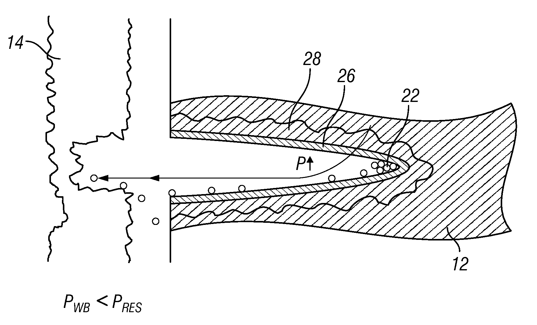
[0010]Accordingly, the present invention provides a method of reducing the effects experienced when using conventional perforators in heterogeneous formations. In particular, the proposed method allows for the enhancement of a dynamic underbalance effect without a decrease in overall perforation efficiency by using reactive shaped charges within the charge carrier of a perforation gun. Thus, it provides an improved method for reducing the shot density to create a dynamic underbalance while delivering a greater overall number of effective perforations. Despite reducing the number of charges within the gun, and allowing a reduction in shot density, effective shot density is not compromised. Moreover, the propensity for gun swell is reduced thereby reducing the risk of difficulty retrieving spent guns from the wellbore. In addition, the method proposed herein achieves a superior inflow and outflow performance compared to that achieved with conventional shaped charges under the same perforating conditions. It further enhances the parameters and effects of injection to enhance and stimulate the production of oil and gas.

Problems solved by technology

Perforation using shaped explosive charges is inevitably a violent event, resulting in plastic deformation of the penetrated rock, grain fracturing, and the compaction of particulate debris (casing material, cement, rock fragments, shaped charge fragments) into the pore throats of rock surrounding the tunnel.
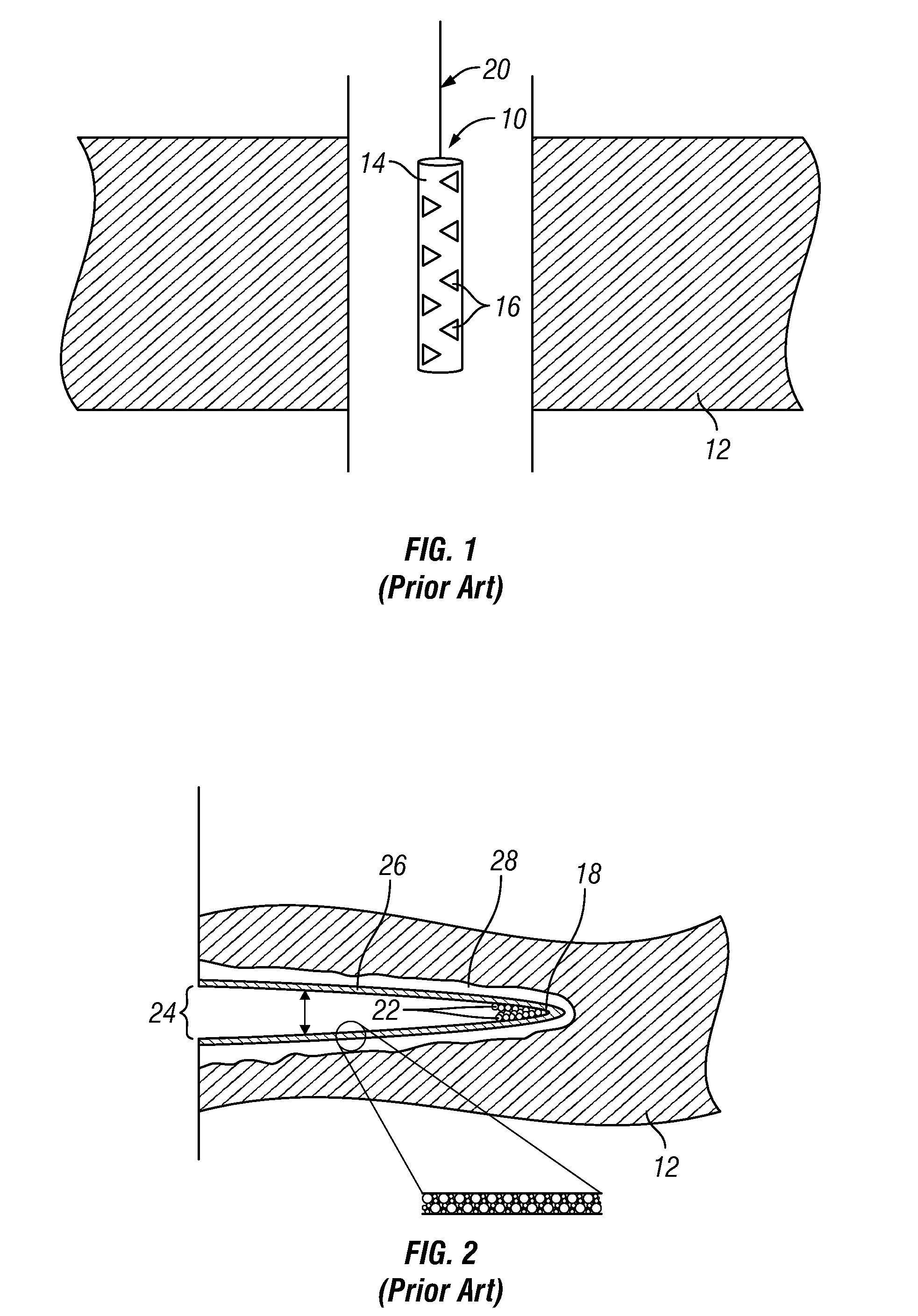
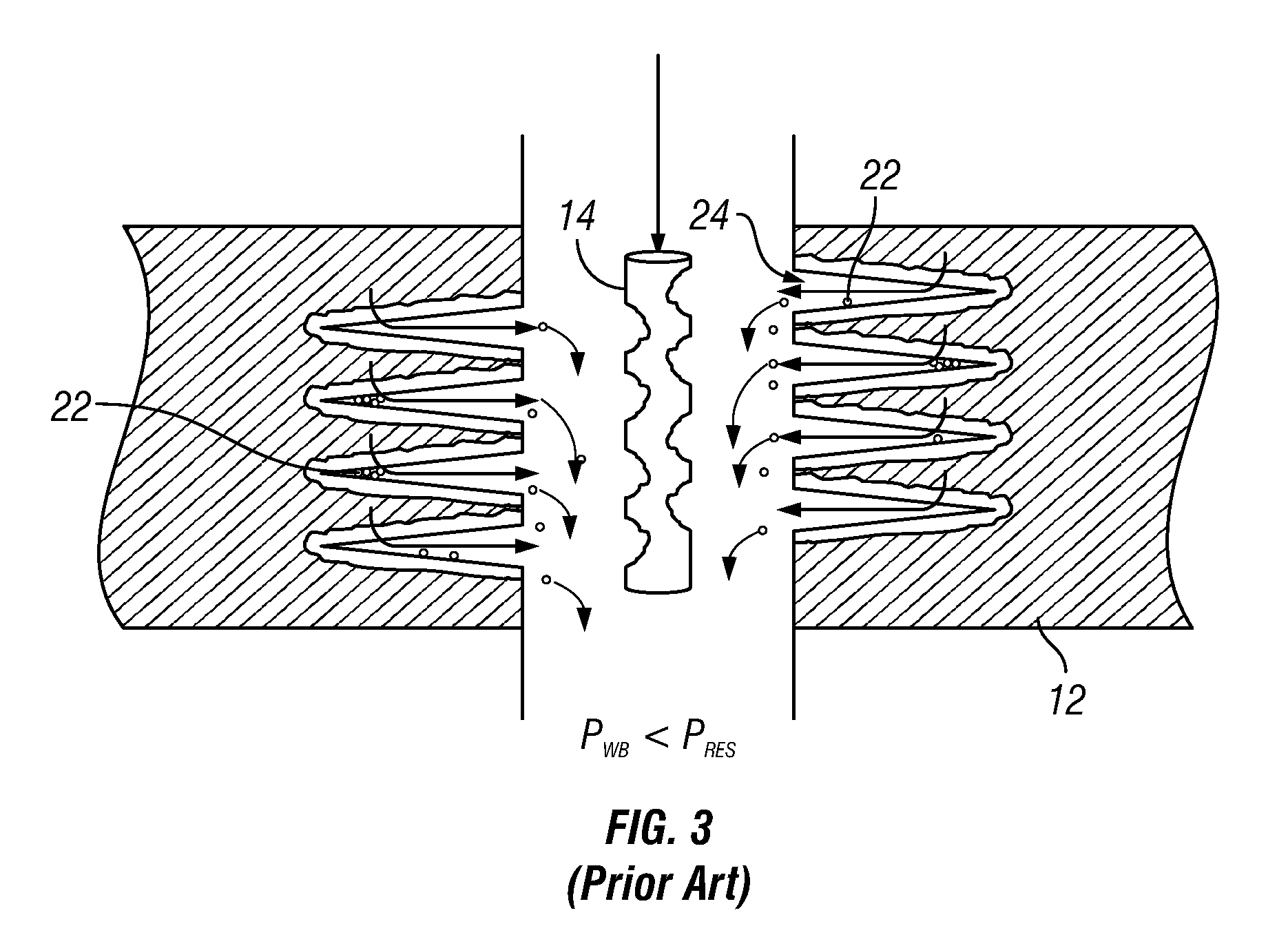
Thus, while perforating guns do enable fluid production from hydrocarbon bearing formations, the effectiveness of traditional perforating guns is limited by the fact that the firing of a perforating gun leaves debris 22 inside the perforation tunnel and the wall of the tunnel.
Plastic deformation of the rock also results in a semi-permanent zone of increased stress 28 around the tunnel, known as a “stress cage”, which further impairs fracture initiation from the tunnel.
Currently, there is no means of measuring it in the borehole.
This becomes even more significant when near-wellbore formation damage has occurred during the drilling and completion process, for example, resulting from mud filtrate invasion.
If the effective penetration is less than the depth of the invasion, fluid flow can be seriously impaired.
However, if the reservoir pressure and / or formation permeability is low, or the wellbore pressure cannot be lowered substantially, there may be insufficient driving force to remove the debris.
Thus, in a number of situations, it is difficult or even impossible to create a sufficient pressure gradient between the formation and the wellbore.
For example, in heterogeneous formations—where rock properties such as hardness and permeability vary significantly within the perforation interval—and in formations of high-strength, high effective stress and / or low natural permeability, underbalanced techniques become increasingly less effective.
Since the maximum pressure gradient is limited by the difference between the reservoir pressure and the minimum hydrostatic pressure that can be achieved in the wellbore, perforations shot into low permeability rock may never experience sufficient surge flow to clean up.
However, this generally calls for a reduction in the number of shaped charges within the gun and therefore, a reduction in shot density and an increased risk of low perforation efficiency.
Low perforation efficiency, inadequately cleaned tunnels and / or insufficient shot density limits the overall inflow and / or outflow potential of the well and the area through which fluids can flow, causing increased pressure drop and erosion and impairing fracture initiation and propagation.

Method used


Image

  • Method for the Enhancement of Dynamic Underbalanced Systems and Optimization of Gun Weight
  • Method for the Enhancement of Dynamic Underbalanced Systems and Optimization of Gun Weight
  • Method for the Enhancement of Dynamic Underbalanced Systems and Optimization of Gun Weight

Examples


Embodiment Construction

[0020]The present invention provides an improved method for the perforation of a wellbore and the creation of a local dynamic underbalance effect within a charge carrier without comprising shot density. In adjusting the free volume of the gun to create a dynamic underbalance, there is a trade off between cleaning out the debris from within a perforated tunnel and a reduction in the total number of holes perforated. In order to maximize the sustained dynamic underbalance pressure within and around a perforating gun, the free gun volume must be increased, resulting in less total shots into the formation. That is, by reducing the number of shaped charges loaded within a perforating gun from the normal fully-loaded amount, an enhanced dynamic underbalance effect is achieved. By using reactive shaped charges, the present invention allows for the use of fewer charges (to enhance dynamic underbalance effects) and yet reduces the risk of low perforation efficiency. By induction of a second ...


PUM


Abstract

By using reactive shaped charges, a dynamic underbalance effect associated with detonation of a perforating system is enhanced without compromising shot density. Fewer shaped charges can be loaded to achieve the same or better effective shot density as a gun fully loaded with conventional shaped charges, thereby increasing the free volume within the gun while creating debris-free tunnels with fractured tips and substantially eliminating the crushed zone surrounding each perforated tunnel. Further, the strength and grade of gun steel required to construct the gun can be reduced without compromising the amount the gun swells following detonation.

Description

CROSS-REFERENCE TO RELATED APPLICATION[0001]This application claims priority to provisional application Ser. No. 61 / 118,997, filed Dec. 1, 2008.TECHNICAL FIELD[0002]The present invention relates generally to reactive shaped charges used in the oil and gas industry to explosively perforate well casing and underground hydrocarbon bearing formations, and more particularly to an improved method for explosively perforating a well casing and its surrounding underground hydrocarbon bearing formation while enhancing the efficacy of dynamic underbalanced systems and reducing overall shot density and cost.BACKGROUND OF THE INVENTION[0003]Wellbores are typically completed with a cemented casing across the formation of interest to assure borehole integrity and allow selective injection into and / or production of fluids from specific intervals within the formation. It is necessary to perforate this casing across the interval(s) of interest to permit the ingress or egress of fluids. Several method...

Claims


Application Information

Patent Timeline
Patent Type & Authority Applications(United States)
IPC IPC(8): E21B43/117
CPCE21B43/1195E21B43/117E21B21/085
Inventor BELL, MATTHEW ROBERT GEORGEWESSON, DAVID S.CLARK, NATHAN GARRETHARDESTY, JOHN THOMAS
Owner WELLS FARGO BANK NAT ASSOC
Learn More