Intramedullary Arthrodesis Nail and Method of Use

a technology of intramedullary arthrodesis and nail, which is applied in the field of intramedullary arthrodesis nail, can solve the problems of ulno-carpal abutment or impingement, and achieve the effects of reducing excessive bone resection, persistent tenderness, and tendon damag

Active Publication Date: 2010-05-27
SKELETAL DYNAMICS INC
View PDF21 Cites 49 Cited by
  • Summary
  • Abstract
  • Description
  • Claims
  • Application Information

AI Technical Summary

Benefits of technology

[0017]It is accordingly an object of this invention to provide a multi-part intramedullary device for total arthrodesis which permits the surgeon to, intraoperatively, select and adjust on all planes the optimum alignment of the bones to be fused. The device is affixed primarily within the bones of the patient in order to minimize excessive bone resection, tendon damage, persistent tenderness after implantation and the consequential need for device removal.

Problems solved by technology

It should be noted, however, that known types of plates that are attached to the dorsal aspect of the wrist, such as those described above, have significant drawbacks: (i) achieving the desired ulnar deviation sometime requires the longitudinal axis of the plate to be placed somewhat obliquely to the axis of the radius; (ii) significant bone resection of the dorsal side of the radius, lunate, capitate and metacarpal bones is often required in order to allow the plate to lie flat on the bones to be fused; (iii) the long incision required to install the plate sometimes leads to wound healing problems, dehiscense or infection; (iv) plate and / or screw prominence can lead to tenosynovitis, tendon rupture or tendon adhesion requiring later tenolysis; (v) shortening of the carpus can result in ulno-carpal abutment or impingement; (vi) bone fractures near the ends of the fusion plates can occur even after solid healing of the joint and (vii) persistent tenderness at the location of the implant.

Method used


Image

  • Intramedullary Arthrodesis Nail and Method of Use
  • Intramedullary Arthrodesis Nail and Method of Use
  • Intramedullary Arthrodesis Nail and Method of Use

Examples


Embodiment Construction

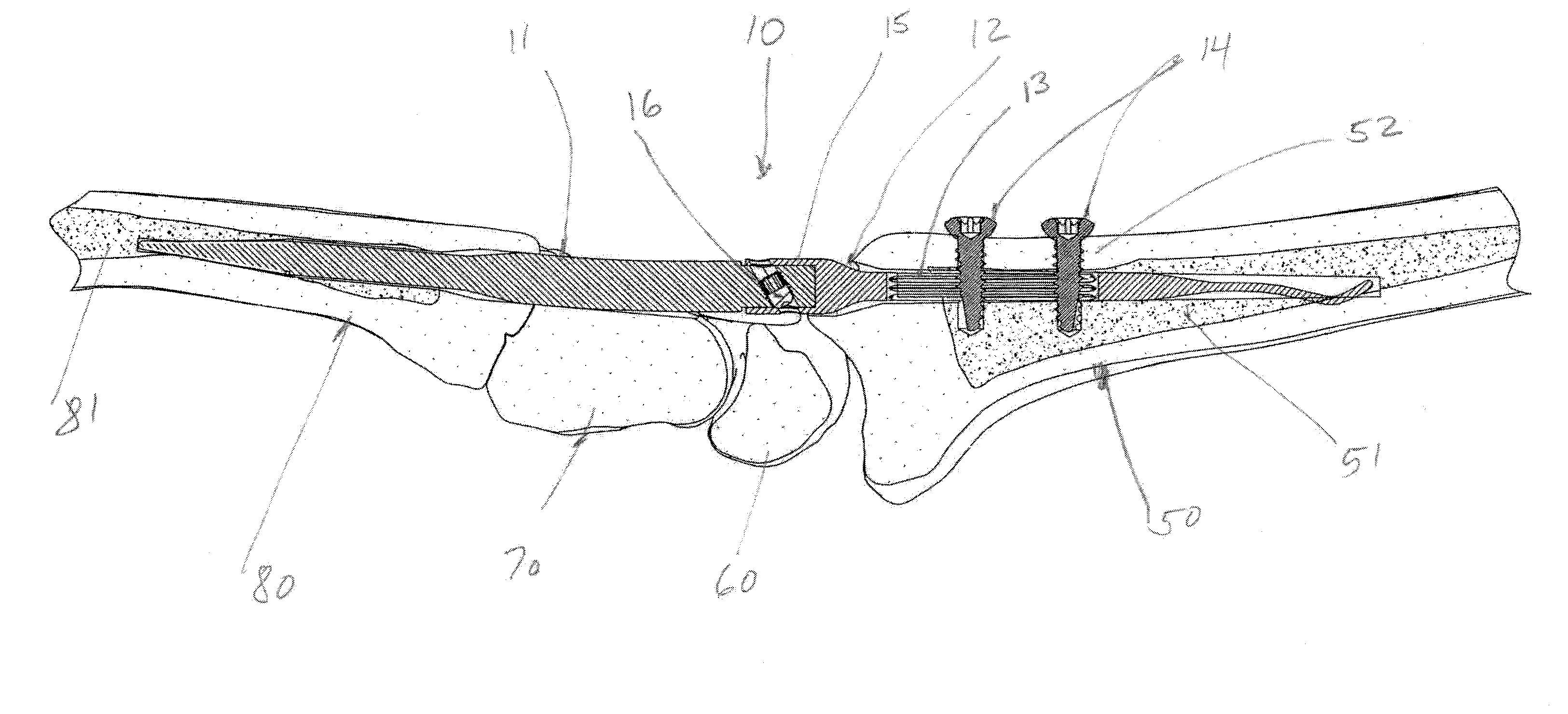
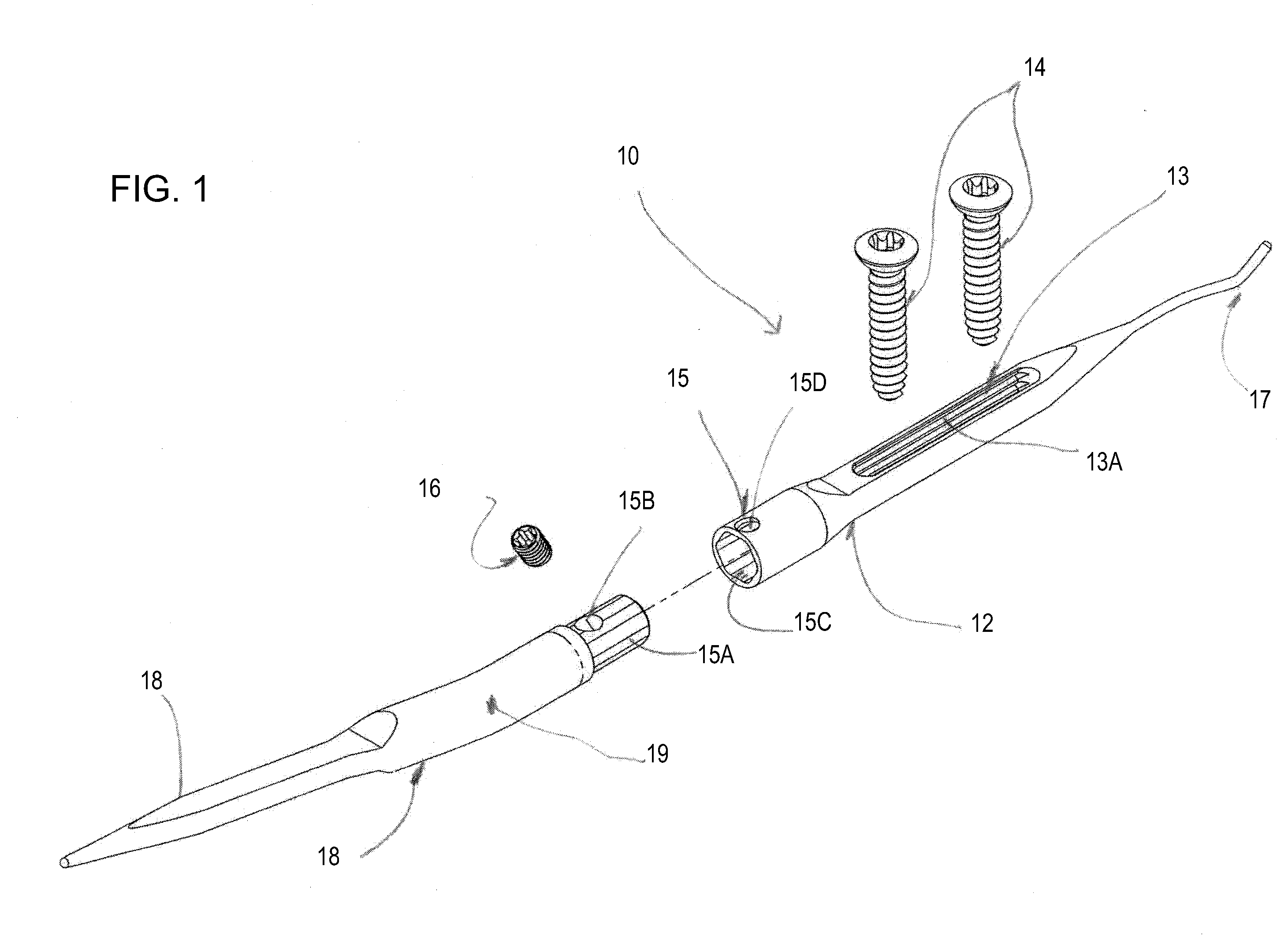
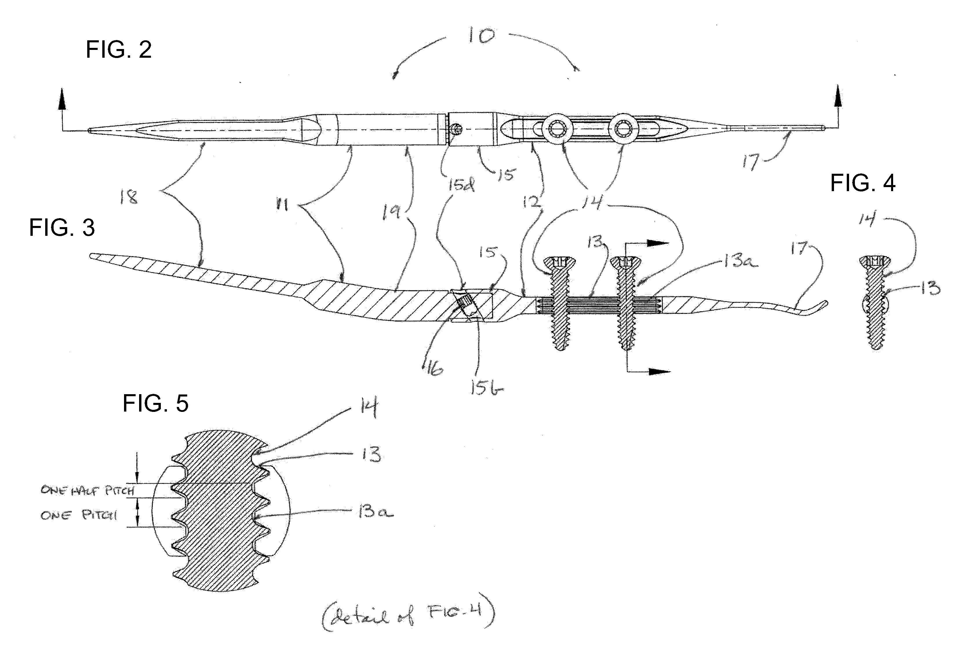
[0044]Referring now to the figures of the drawings in detail and more particularly to FIGS. 1, 2 and 3 there is shown one particular embodiment of a multi-part intramedullary arthrodesis nail of the instant invention for performing arthrodesis of the wrist. The intramedullary arthrodesis nail is designed to be placed internally within selected bones of the wrist in order to immobilize the joint during a sufficient period of time to allow the permanent fusion of the selected bones, and in some cases, some adjacent bones of the wrist. The internal placement of the intramedullary arthrodesis nail minimizes incision length, excessive bone resection, tendon damage and persistent tenderness after implantation.

[0045]The intramedullary arthrodesis nail shown on FIGS. 1, 2 and 3 is a multi-part device and is preferably made of biocompatible metal (such as titanium, cobalt chrome or stainless steel) or bioabsorbable material (such as PLA or PGA) or a combination of metal and bioabsorbable mat...


PUM

PropertyMeasurementUnit
angleaaaaaaaaaa
lengthaaaaaaaaaa
degrees of movementaaaaaaaaaa

Abstract

A device is provided including a distal nail portion and a proximal nail portion that can be connected to each other to attain a rigid configuration. The device is to be placed internally within the medullary cavities of at least two bones forming a joint to accomplish arthrodesis of the joint. The device is placed intramedullarily in order to minimize incision size, excessive bone resection and post-operative tendon damage and tenderness. Additionally, one particular method for using the device is provided that includes placing and affixing the distal nail in a bone of a joint, placing the proximal nail in another bone of a joint, connecting the distal nail to the proximal nail, doing the desired geometrical adjustments, affixing the proximal nail to the distal nail by tightening the connection and affixing the proximal nail to the other bone of the joint to attain a rigid configuration.

Description

CROSS-REFERENCE TO RELATED APPLICATIONS[0001]The present application claims priority to: co-pending Provisional Patent Application No. 61 / 097,616, filed on Sep. 17, 2008 and co-pending Provisional Patent Application No. 61 / 239,277, filed on Sep. 2, 2009 both entitled “Intramedullary Arthrodesis Nail and Method of Use”; those applications being incorporated herein, by reference, in their entireties.FIELD OF THE INVENTION[0002]The instant invention relates to arthrodesis, also known as joint fusion, the surgically induced permanent fusion of two or more bones concurring in a joint.BACKGROUND OF THE INVENTION[0003]Arthrodesis or joint fusion is a well known procedure often associated with the spine, the ankle or the wrist. In particular, the wrist or carpus is the complex joint between the forearm and the hand. It allows the hand three degrees of movement important to manual dexterity: flexion / extension in the palmar-dorsal plane; adduction / abduction, also referred to as radial or ulna...

Claims


Application Information

Patent Timeline
Patent Type & Authority Applications(United States)
IPC IPC(8): A61B17/58A61B17/56
CPCA61B17/1717A61B2017/1782A61B17/7225A61B17/7241A61B17/7291A61F2/4261A61F2002/30062A61F2002/30331A61F2002/30481A61F2002/30507A61F2002/30538A61F2002/3054A61F2002/30622A61F2002/30774A61F2002/30777A61F2002/4264A61F2210/0004A61F2220/0025A61F2220/0033A61F2250/0006A61B17/1725A61B17/1782A61B17/72A61B17/7283
Inventor ORBAY, JORGE L.NORMAN, THOMAS H.SALCEDO, JUANLITKE, RONALD
Owner SKELETAL DYNAMICS INC
Why Eureka
Try Eureka