
Sensor network system, transmission protocol, method for recognizing an object, and a computer program

a technology of a network system and a sensor, applied in the field of sensor network system for tracking moving objects, can solve problems such as challenging the technology of tracking moving objects from one monitored subregion to the next, and achieve the effect of reducing the difficulty of detecting the movement of objects

Inactive Publication Date: 2010-05-27
ROBERT BOSCH GMBH
View PDF5 Cites 23 Cited by
  • Summary
  • Abstract
  • Description
  • Claims
  • Application Information

AI Technical Summary

Benefits of technology

The present invention provides a sensor network system for tracking moving objects in a surveillance region. The system includes a plurality of network nodes, each assigned to a subregion of the surveillance region. The network nodes include a classifier generator and a classifier evaluator. The classifier generator is designed to train a local classifier for the network node or the subregion to which it is assigned. The classifier evaluator is designed to apply the local classifier on a moving object observed by the network node. The network nodes forward object information on the moving objects to other network nodes, which helps in tracking the objects within the surveillance region. The invention also provides a method for recognizing objects using a learning process and a computer program for the same. The technical effects of the invention include improved object tracking, reduced data transmission, and improved efficiency of the sensor network system.

Problems solved by technology

Since surveillance regions of this type are highly complex in design and typically include intermediate regions that are not monitored, it is technically challenging to track a moving object from one monitored subregion to the next monitored subregion.

Method used


Image

  • Sensor network system, transmission protocol, method for recognizing an object, and a computer program
  • Sensor network system, transmission protocol, method for recognizing an object, and a computer program
  • Sensor network system, transmission protocol, method for recognizing an object, and a computer program

Examples


Embodiment Construction

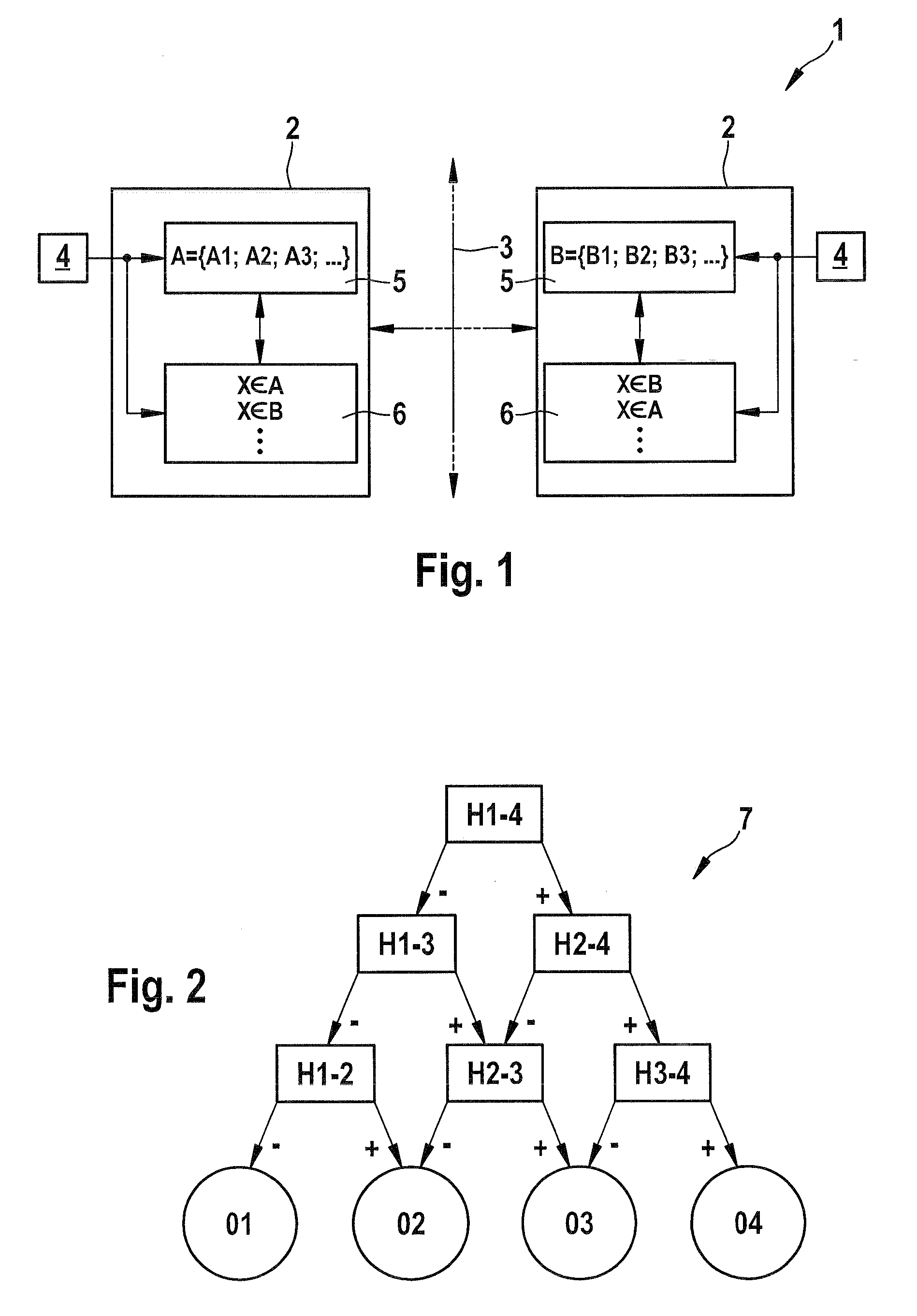
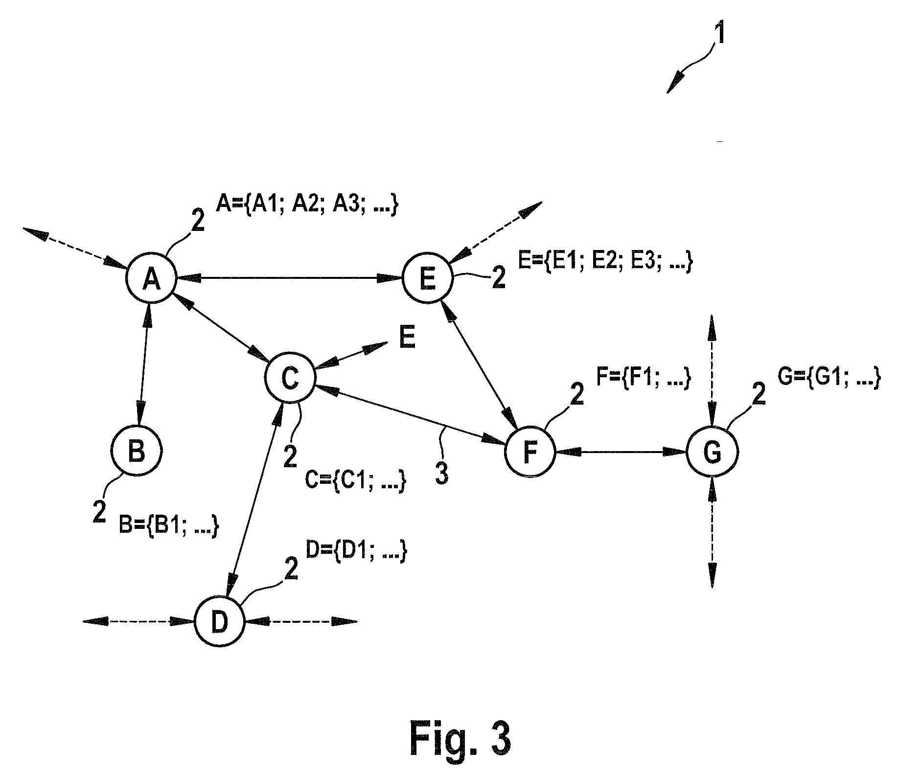
[0034]FIG. 1 shows a schematic block diagram of a sensor network system 1 which is suited and / or designed to monitor a surveillance region, e.g., a building, a street, or the like. Sensor network system 1 comprises a plurality of network nodes 2 which are connected and / or are connectable such that they communicate with one another via a network 3. Network 3 may have any type of design, and, in particular, is connected via cable or wirelessly, e.g, as a LAN, WLAN, Internet, etc. Sensor network system 1 may include a large number, e.g., more than 50 or 100, network nodes 2.

[0035]Network node 2 is connected to one or more sensors 4; sensors 4 of one of the network nodes 2 are directed to a subregion of the surveillance region assigned to network node 2. Sensor 4 may be designed, e.g., as one or more surveillance cameras, or as a microphone, a weight sensor, a sensor for electromagnetic radiation, etc. Using sensors 4, moving objects such as persons in the assigned subregion are detecte...


PUM


Abstract

A sensor network system for tracking moving objects within a surveillance region includes a plurality of network nodes, each assigned and / or assignable to a subregion of the surveillance region, in which at least one of the network nodes includes a classifier generator which is programmed and / or electronically configured to train a local classifier to discriminate the moving objects that are relevant in the assigned subregion, and in which network node is designed to forward object information on the moving objects to other network nodes for the purpose of tracking and / or recognizing moving objects that move away from network node and toward the other network nodes, and in which the object information is designed as classifier.

Description

CROSS-REFERENCE TO A RELATED APPLICATION[0001]The invention described and claimed hereinbelow is also described in German Patent Application DE 10 2008 043 954.1 filed on Nov. 21, 2008. This German Patent Application, whose subject matter is incorporated here by reference, provides the basis for a claim of priority of invention under 35 U.S.C. 119(a)-(d).BACKGROUND OF THE INVENTION[0002]The present invention relates to a sensor network system for tracking moving objects within a surveillance region, comprising a plurality of network nodes, each of which is assigned and / or assignable to a subregion of the surveillance region, in which at least one of the network nodes includes a classifier generator which is programmed and / or electronically configured to train a local classifier to discriminate the moving objects that are relevant in the assigned subregion, and in which the network node is designed to forward object information on the moving objects to other network nodes for the pur...

Claims


Application Information

Patent Timeline
Patent Type & Authority Applications(United States)
IPC IPC(8): G06K9/00H04N7/18G06Q10/00
CPCG06Q10/08G08B13/19602G08B13/1966G08B13/19656G08B13/19643
Inventor WARZELHAN, JAN KARL
Owner ROBERT BOSCH GMBH
Learn More