
Energy-efficient indoor localization system and a method of reducing power consumption of a radio badge in the indoor localization system

a technology of indoor localization system and radio badge, which is applied in the direction of distance measurement, programme control, instruments, etc., can solve the problems of inherently inaccurate prediction of moving velocity and particularly significant adverse effects, and achieve the effect of reducing the power consumption of the radio badg

Active Publication Date: 2010-05-27
NAT TAIWAN UNIV
View PDF5 Cites 31 Cited by
  • Summary
  • Abstract
  • Description
  • Claims
  • Application Information

AI Technical Summary

Benefits of technology

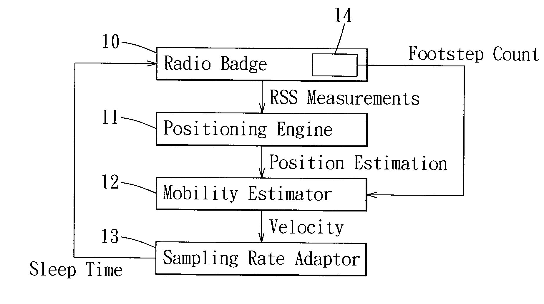
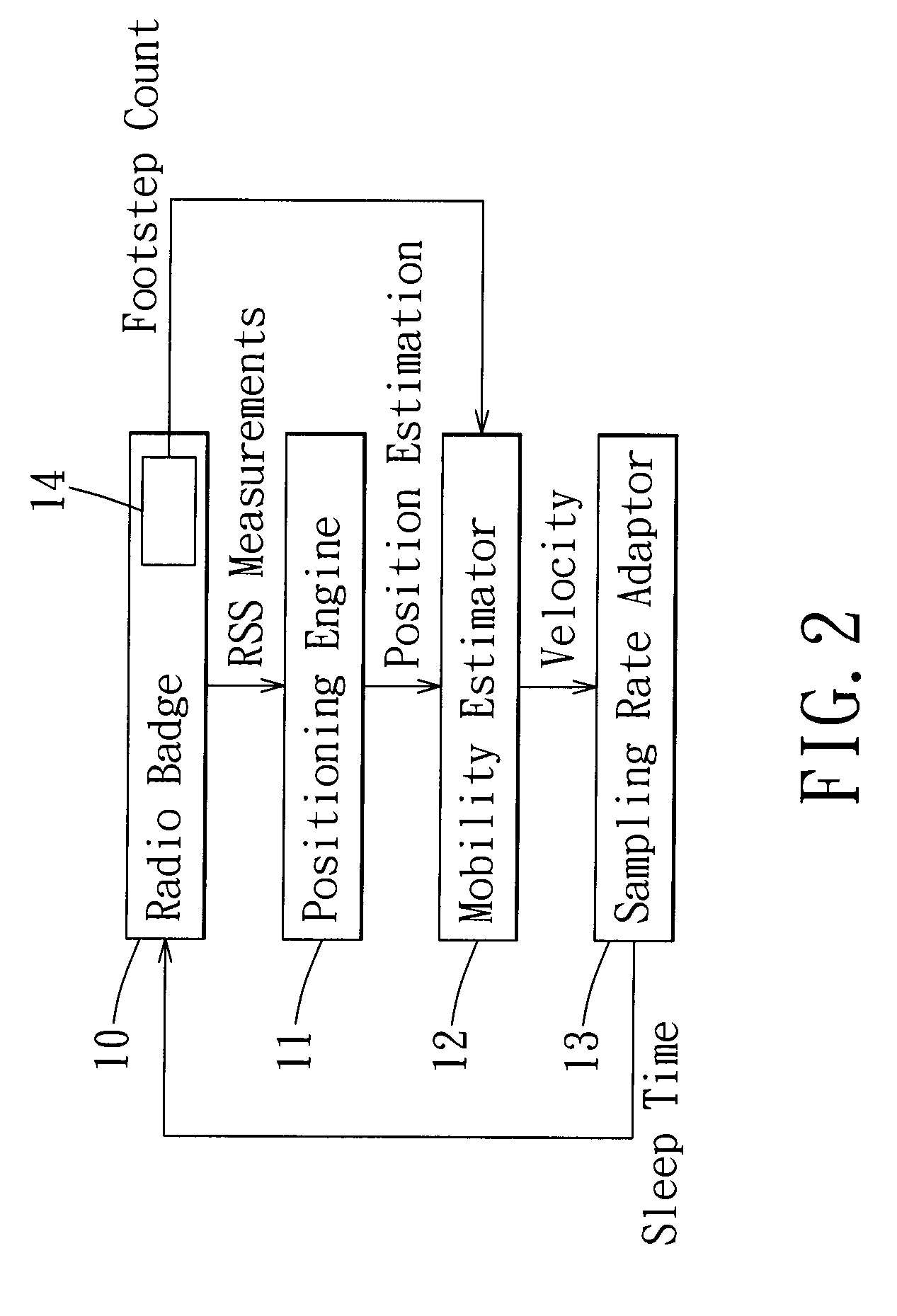
[0010]Therefore, the object of the present invention is to provide an energy-efficient indoor localization method, and a method of reducing power consumption of a radio badge in the indoor localization system, in which a sleep time for the radio badge is determined on the basis of a footstep count of a tracked target carrying the radio badge.
[0011]According to one aspect of this invention, the method of reducing power consumption of a radio badge in a localization system, in which the radio badge is carried by a tracked target and is provided with a pedometer for detecting a footstep count of the tracked target, comprises: estimating a velocity of the radio badge according to the footstep count detected by the pedometer; calculating a sleep time from the velocity of the radio badge; and controlling the radio badge to discontinue emitting radio signals during the sleep time.

Problems solved by technology

There are two main drawbacks in the existing solutions.
The predicted moving velocity is inherently inaccurate due to the position estimation errors.
The adverse effect is particularly significant when the object is static.
The network might continue to sample frequently, erroneously determining that the object is moving due to differences between consecutive position estimations.

Method used


Image

  • Energy-efficient indoor localization system and a method of reducing power consumption of a radio badge in the indoor localization system
  • Energy-efficient indoor localization system and a method of reducing power consumption of a radio badge in the indoor localization system
  • Energy-efficient indoor localization system and a method of reducing power consumption of a radio badge in the indoor localization system

Examples


Embodiment Construction

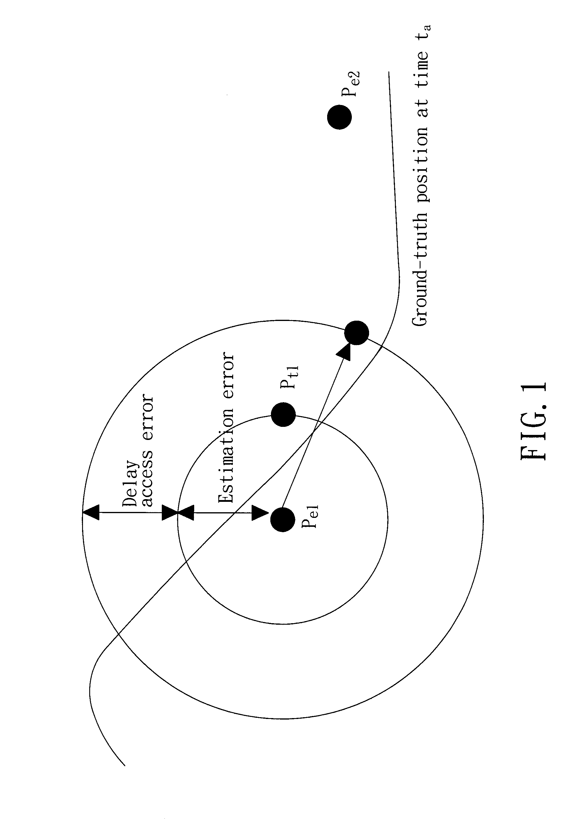
[0017]In formulating the problem to be solved by the present invention, it is assumed that, given a tracked target, a tolerable amount of positional error measured in distance may be specified for a particular application. The positional error is defined as the difference between the actual (ground-truth) position and that reported from a positioning engine.

[0018]Referring to FIG. 1, overall positional error in a localization system comes from two error sources. The first error source is the estimation error from a positioning engine when the positioning engine calculates the position of a tracked target. The positioning engine may mistakenly determine that the object is at Pe1 instead of Pt1 because of measurement problems. The second error source is related to the freshness problem of a location sample within a sampling interval. Two consecutive position samples pe1 and pe2 are calculated for a moving target at times t1 and t2. If an application requests the position of this movin...


PUM


Abstract

A method of reducing power consumption of a radio badge in a localization system is disclosed, in which the radio badge is carried by a tracked target and is provided with a pedometer for detecting a footstep count of the tracked target. The method includes: estimating a velocity of the radio badge according to the footstep count detected by the pedometer; calculating a sleep time from the velocity of the radio badge; and controlling the radio badge to discontinue emitting radio signals during the sleep time. An indoor localization system that performs the method is also disclosed.

Description

CROSS-REFERENCE TO RELATED APPLICATION[0001]This application claims priority of Taiwanese Application No. 097145520, filed on Nov. 25, 2008.BACKGROUND OF THE INVENTION[0002]1. Field of the Invention[0003]The present invention relates to an indoor localization system that is energy efficient, and to a method of reducing power consumption of a radio badge in the indoor localization system, in which a sleep time for the radio badge is determined on the basis of a footstep count of a tracked target carrying the radio badge.[0004]2. Description of the Related Art[0005]Sensor network technologies have experienced significant advances in recent times. This has enabled a variety of applications for sensor networks in consumer electronics. For example, there is an ever-increasing number of commercial and experimental uses of sensor networks for object tracking, such as asset tracking in warehouses, patient monitoring in medical facilities, and using location to infer activities of daily livi...

Claims


Application Information

Patent Timeline
Patent Type & Authority Applications(United States)
IPC IPC(8): H04Q5/22
CPCG01C22/006H04Q2213/13003G01S1/042G01P3/64G01S1/0423
Inventor HUANG, POLLYCHU, HAO-HUAYOU, CHUANG-WEN
Owner NAT TAIWAN UNIV
Learn More