
Signal transmitting device

Active Publication Date: 2010-05-27
TDK CORPARATION
View PDF6 Cites 1 Cited by
  • Summary
  • Abstract
  • Description
  • Claims
  • Application Information

AI Technical Summary

Benefits of technology

[0006]In view of the foregoing, an object of the present invention is to provide a signal transmitting device having a simple circuit configuration.
[0008]According to the signal transmitting device of the present invention, the input signal is converted into the output signal on the basis of the magnetic resistances of the magneto-resistive elements which do not have the memory effect. Therefore, it is unnecessary to shape the waveform of the input current flowing through the first conductor into a pulse signal or the like, and accordingly, the circuit configuration can be simplified. Moreover, it is possible to prevent the noise from being stored due to the memory effect, which ensures high reliability with respect to the noise.
[0010]According to the present invention, the input signal is converted into the output signal on the basis of the magnetic resistance of the magneto-resistive element which does not have the memory, effect. Therefore, the waveform of the input current flowing through the first conductor does not have to be shaped into a pulse signal or the like, and thus, the circuit configuration can be simplified. Moreover, high reliability with respect to the noise is ensured.

Problems solved by technology

This increases the circuit scale as well as cost.
Furthermore, it has been pointed out that the coupler has poor reliability with respect to noise, because if false information is once stored in the magneto-resistive element due to the noise applied from the outside, the false information will be retained in the magneto-resistive element from the time of input of the noise to the time when the logic state of the input signal changes.

Method used


Image

  • Signal transmitting device
  • Signal transmitting device
  • Signal transmitting device

Examples


first embodiment

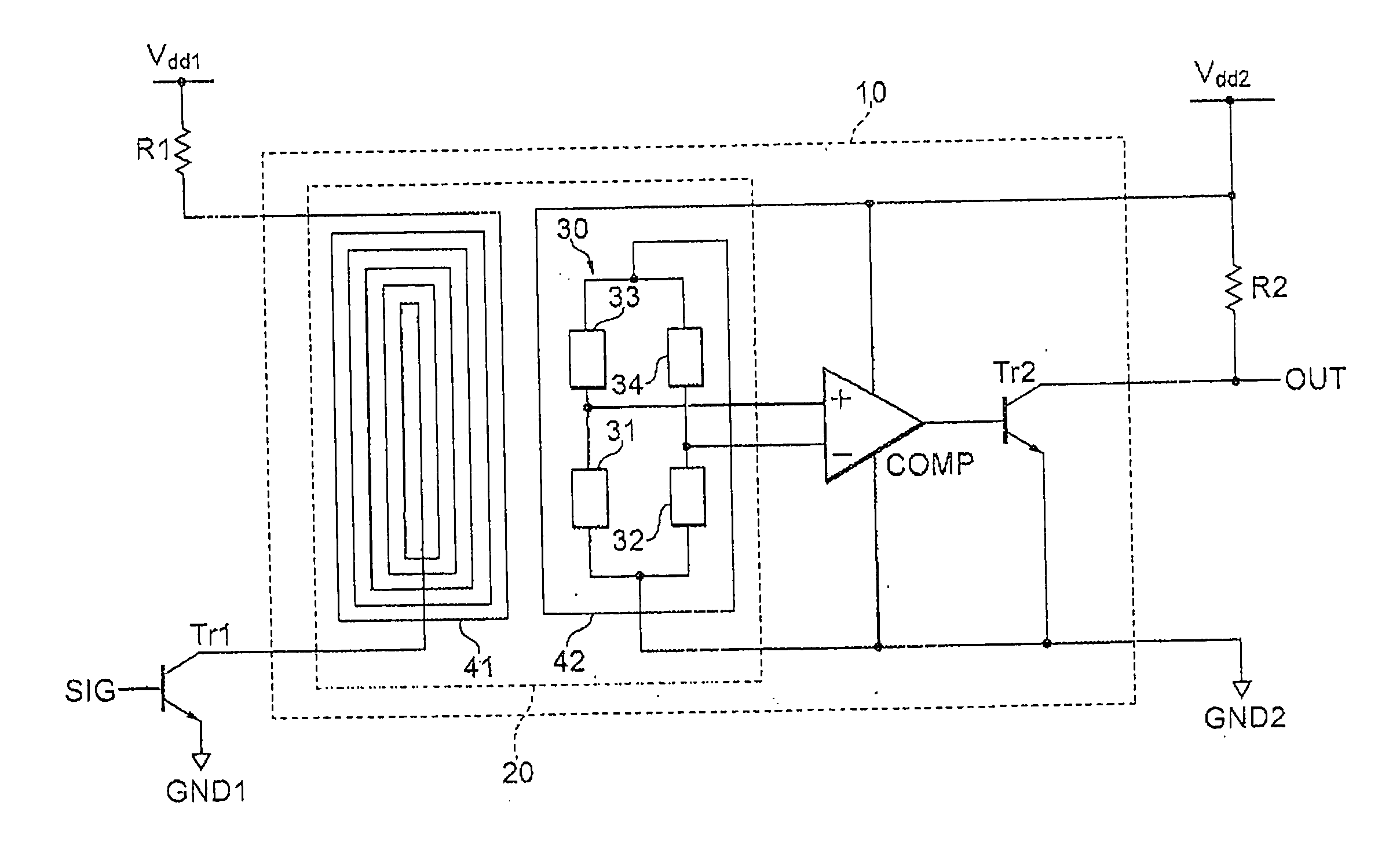
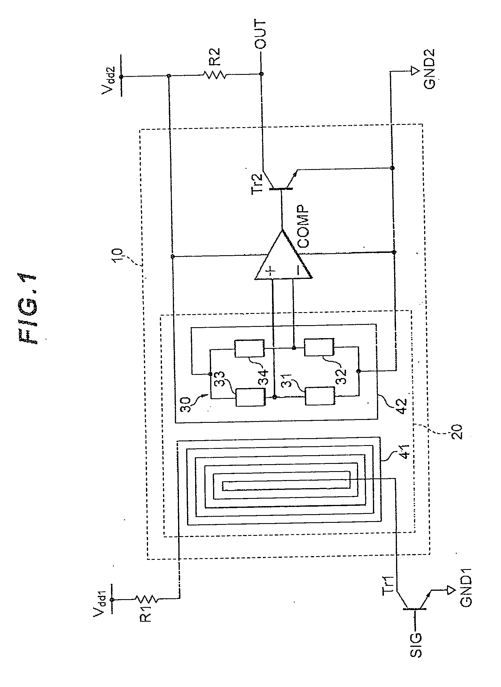
[0022]FIG. 1 is a main circuit diagram of a magnetic coupling-type isolator 10 according to a first embodiment. The magnetic coupling-type isolator 10 is an insulated interface which provides both an electrical insulation between an input and an output and a signal coupling function. The magnetic coupling-type isolator 10 may be referred to as a signal isolation device or a signal transmitting device. The magnetic coupling-type isolator 10 primarily includes a magnetic coupler element 20 and a comparator COMP.

[0023]The magnetic coupler element 20 includes: a primary coil 41 made up of a conductor through which an input current as an input signal flows; a detection bridge circuit 30 having a plurality of magneto-resistive elements 31, 32, 33, and 34 bridge-connected with each other; and a bias coil 42 made up of a conductor through which a bias current as a bias signal flows. The detection bridge circuit 30 has a circuit configuration in which a set of the two magneto-resistive eleme...

second embodiment

[0044]FIG. 9 is a main circuit diagram of a magnetic coupling-type isolator 50 according to a second embodiment of the present invention. The configuration of the second embodiment is identical to that of the first embodiment except that the detection bridge circuit 30 in the magnetic coupling-type isolator 50 has a circuit configuration in which a set of a magneto-resistive element 31 and a resistance element 35 connected in series and a set of a magneto-resistive element 32 and a resistance element 36 connected in series are connected in parallel. The resistance element 35 and the resistance element 36 preferably have the same resistance value, and more preferably have the same temperature-resistance characteristics. The magnetic coupling-type isolator 50 according to the second embodiment has the functions similar to, and exerts the functional effects similar to, those of the magnetic coupling-type isolator 10 of the first embodiment.

third embodiment

[0045]FIG. 10 is a main circuit diagram of a magnetic coupling-type isolator 60 according to a third embodiment of the present invention. The configuration of the third embodiment is identical to that of the first embodiment except that the detection bridge circuit 30 in the magnetic coupling-type isolator 60 has a circuit configuration in which a set of a magneto-resistive element 31 and a constant current source 37 connected in series and a set of a magneto-resistive element 32 and a constant current source 38 connected in series are connected in parallel. The constant current source 37 and the constant current source 38 preferably supply the current of the same value to the magneto-resistive element 31 and the magneto-resistive element 32, respectively. The use of the constant current sources 37 and 38 enables implementation of the detection bridge circuit 30 including only two magneto-resistive elements 31 and 32 as shown in FIG. 10, unlike the detection bridge circuit 30 shown ...


PUM


Abstract

A magnetic coupling-type isolator includes a primary coil configured to generate a first magnetic field in accordance with an input signal, a bias coil configured to generate a second magnetic field in accordance with a bias signal, a first magneto-resistive element having a magnetic resistance increased by the first magnetic field and decreased by the second magnetic field, a second magneto-resistive element having a magnetic resistance decreased by the first magnetic field and increased by the second magnetic field, and a comparator configured to output an output signal in accordance with a difference between the magnetic resistance of the first magneto-resistive element and the magnetic resistance of the second magneto-resistive element.

Description

BACKGROUND OF THE INVENTION[0001]1. Field of the Invention[0002]The present invention relates to a signal transmitting device which converts an input signal into an output signal by detecting a change in intensity of a magnetic field caused by a change of the input signal as a change in magnetic resistance of a magneto-resistive element.[0003]2. Description of the Related Art[0004]A magnetic coupling-type isolator may be used as an isolator for transmitting a digital or analog signal, and is applied, e.g., to an interface for connecting a computer with its peripheral device, an interface for connecting between circuits of different potentials, or an interface for use in a relay transmission device on a communication network. The magnetic coupling-type isolator provides an electrical insulation between an input and an output, and also detects a change in intensity of the magnetic field caused by a change of the input signal as a change in magnetic resistance of a magneto-resistive el...

Claims


Application Information

Patent Timeline
IPC IPC(8): H03H2/00
CPCB82Y25/00G08C17/04G01R33/093
Inventor IMAI, TAKAKAZUOKUNO, REIJI
Owner TDK CORPARATION
Learn More