
System and method for sensing the periodic position of an object

a technology of periodic position and sensing method, which is applied in the field of electronic equipment, can solve the problems of insufficient bandwidth of combined resistance and inductance of wire and coil, inability to accurately measure the output signal of passive eddy current sensors, and inability to detect the position of objects with periodic position, etc., to achieve the effect of greater target sensitivity, high bandwidth capability and rugged circuitry

Active Publication Date: 2010-05-27
GENERAL ELECTRIC CO
View PDF11 Cites 8 Cited by
  • Summary
  • Abstract
  • Description
  • Claims
  • Application Information

AI Technical Summary

Benefits of technology

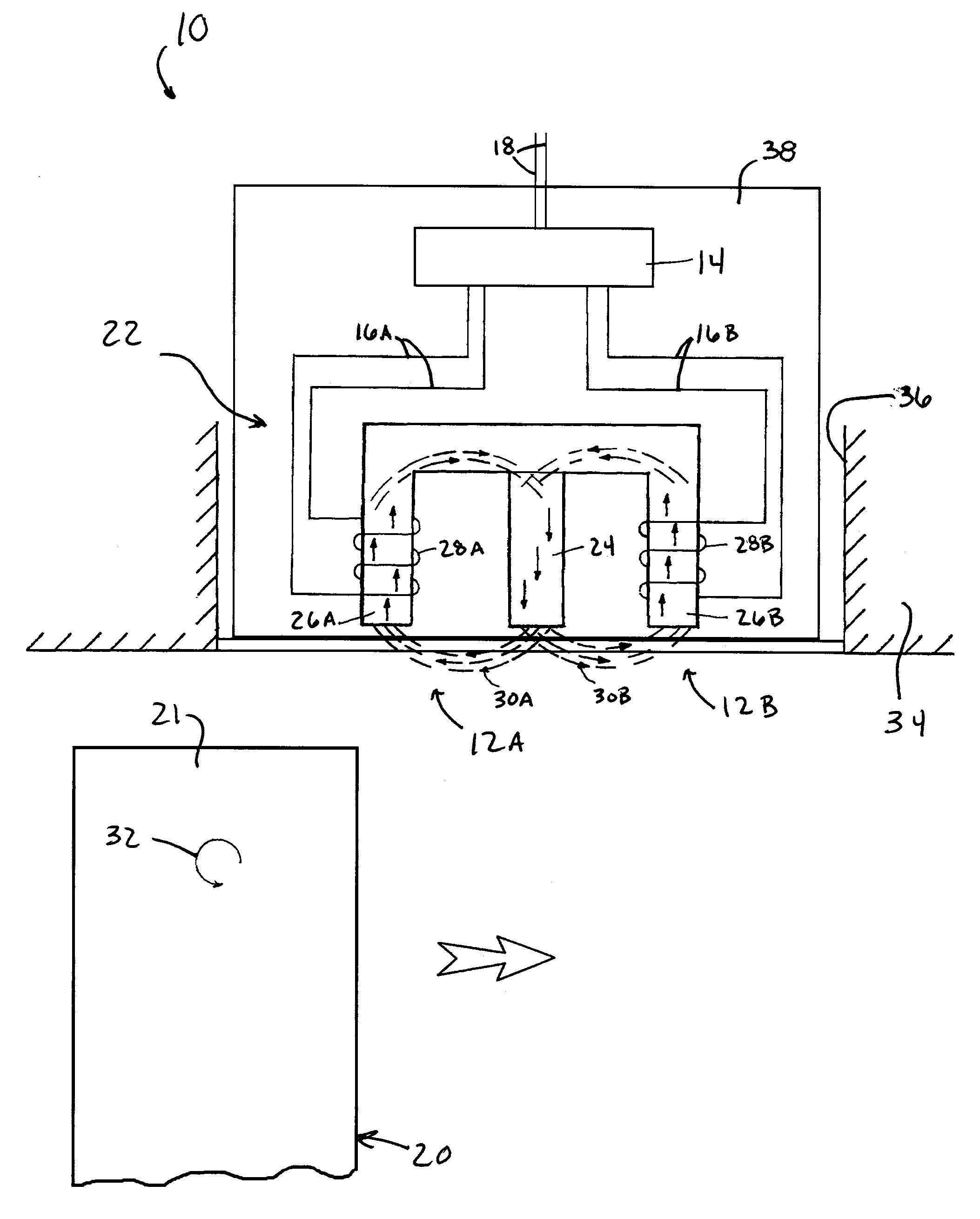
"The present invention provides a system and method for sensing the arrival, position, and vibration of moving objects, such as rotating blades of a turbine. The system includes a passive eddy current sensing unit that uses magnets and coils to generate and detect magnetic fields. The sensing unit is positioned relative to the object so that it passes through the magnetic fields in succession, and the coils produce output signals in response. The output signals are then electronically combined to produce an output that represents the timing of the object as it passes through the magnetic fields. The system is designed to have a clean sinusoidal waveform and is resistant to electromagnetic interference. The method is also suitable for use as a blade position sensor system in a gas turbine engine. The invention has the advantage of being a multi-coil probe design with high bandwidth and target sensitivity, as well as being a rugged and high-temperature-capable system that does not require active cooling."

Problems solved by technology

Passive eddy current sensors are susceptible to electromagnetic interference (EMI) noise due to the many turns of wire typically present and required in the construction of their cores, as well the long cable runs between the sensor and the engine FADEC.
The coils are connected in series with a simple wire connection, with the result that EMI and other unwanted disturbances are subtracted from the output signal of the sensor.
Evaluations of passive eddy current sensors configured in accordance with Gallant have shown that the combined resistance and inductance of the wire and coils are too great for the sensor to have sufficient bandwidth to accurately sense the position and vibrations of individual airfoils.
Such sensors also suffer from output wave shape limitations.
However each of these sensor designs suffers from decreased bandwidth and waveshape variations due to the combined resistance and inductance associated with having two coils wired in series.
However, neither appears to address the issue of operating in an EMI environment, and therefore these prior sensors do not appear to be capable of producing reliable measurements in a high EMI environment.

Method used


Image

  • System and method for sensing the periodic position of an object
  • System and method for sensing the periodic position of an object
  • System and method for sensing the periodic position of an object

Examples


Embodiment Construction

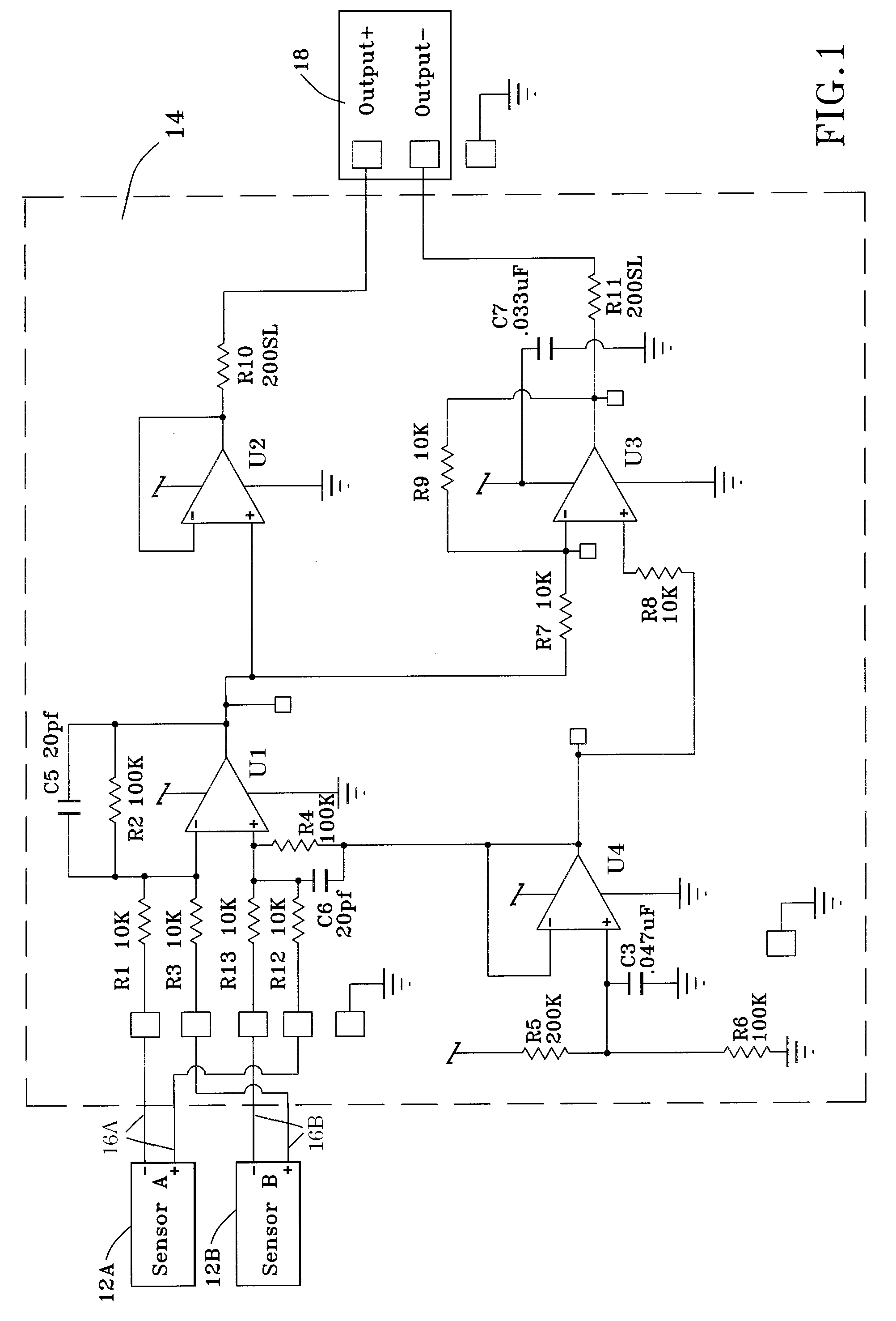
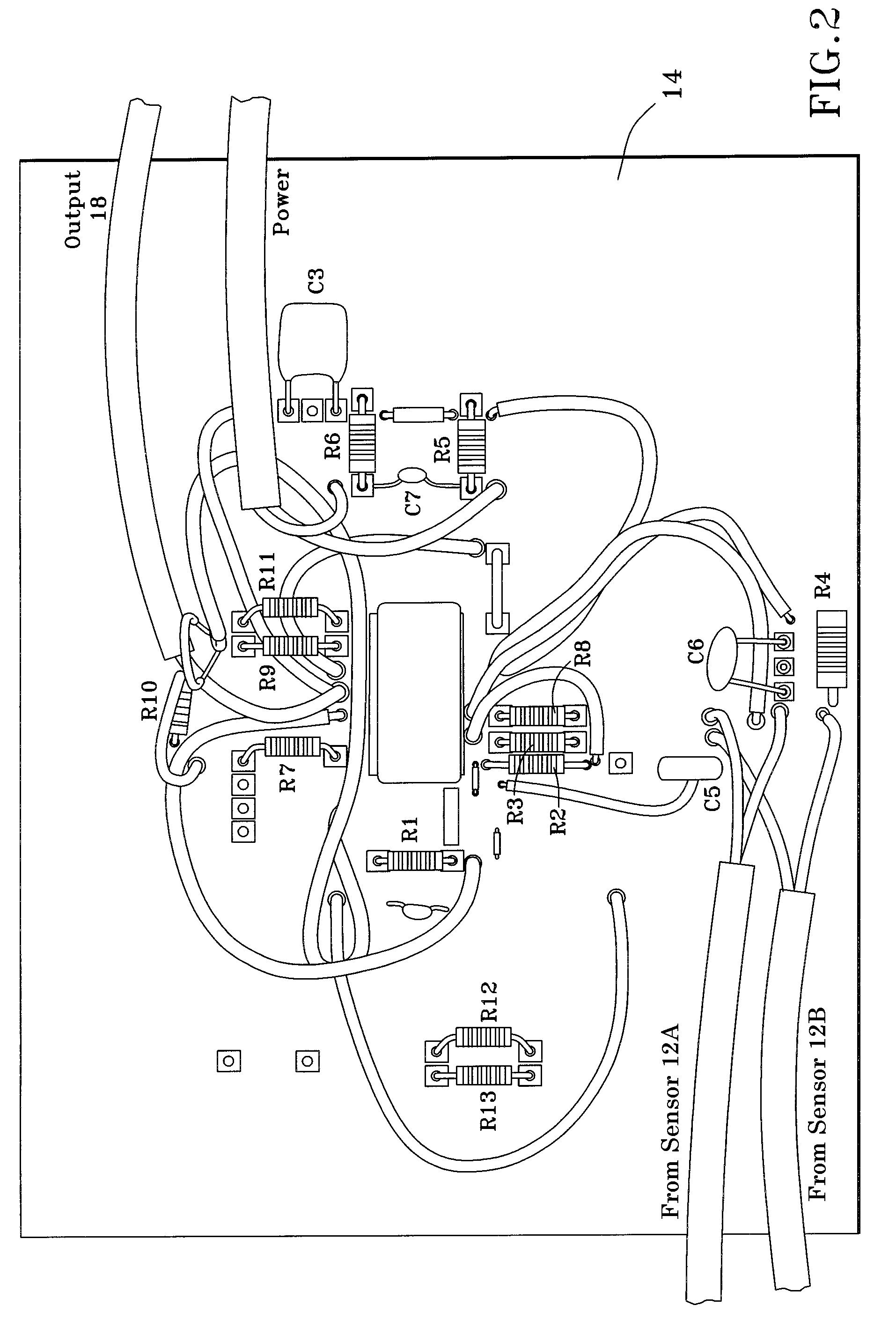
[0019]FIG. 1 is an electrical schematic of a sensing system 10 containing two passive eddy current sensors 12A and 12B coupled to analog electronic processing circuitry 14 that electronically combines separate output signals 16A and 16B of the sensors 12A and 12B, respectively. The processing circuitry 14 combines the output signals 16A-B of the sensors 12A-B in a manner that eliminates EMI noise from the system output 18 generated by the circuitry 14 by canceling any EMI noise present in the output signals 16A-B of the sensors 12A-B, as well as provides gain to the output signals 16A-B, with the result that the system 10 is also capable of exhibiting a high bandwidth capability and greater target sensitivity. The system 10 and sensors 12A-B will be discussed as particularly well suited for sensing the position of rotating equipment, such as blades (buckets) 20 of a gas turbine engine as represented in FIG. 4, though other applications are foreseeable. In such an application, after ...


PUM


Abstract

A system and method for sensing the periodic position of one or more objects, such as rotating blades of a turbine. The system includes a passive eddy current sensing unit having one or more magnets and first and second cores around which first and second coils are wound, respectively, which together generate first and second magnetic fields. The sensing unit is positioned so that the object periodically passes through the first and second magnetic fields in succession, and the first and second coils consequently produce first and second output signals, respectively. Each coil is individually connected to a processing circuitry that receives each of the first and second output signals. The circuitry electronically combines the first and second output signals so that common mode signals thereof electronically subtract from each other to eliminate from output of the circuitry any electromagnetic interference noise present in the first and second output signals.

Description

BACKGROUND OF THE INVENTION[0001]The present invention generally relates to electronic equipment, and more particularly to a system that utilizes passive eddy current sensors to sense rotating equipment, such as the arrival, position, and / or vibration of turbine blades and other moving objects.[0002]Passive eddy current sensors and variable reluctance sensors have been employed in a wide variety of applications to sense the proximity and speed of rotating equipment, including blades (buckets) of gas turbines. Another application is to sense the positions of rotating blades within the fan, booster, compressor and turbine sections of a gas turbine engine to monitor the health of the engine. In particular, the output of a passive eddy current sensor (or other suitable position sensor) can be used to monitor blade vibrations and steady-state blade circumferential positions over the life of the engine. Changes in blade vibrations or blade static positions can indicate damage to the compo...

Claims


Application Information

Patent Timeline
Patent Type & Authority Applications(United States)
IPC IPC(8): G01B7/30G01B7/00
CPCG01B7/30G01B7/003
Inventor WEICKERT, JOHN
Owner GENERAL ELECTRIC CO
Learn More