Thin-plate container

a container and plate technology, applied in the field of thin plate containers, can solve the problems of easy generation of dust particles, difficult to meet the requirements of the application, and difficult to meet the requirements of the application, and achieve the effect of good air tightness and good air tightness

Inactive Publication Date: 2010-05-27
GUDENG PRECISION IND CO LTD
View PDF23 Cites 10 Cited by
  • Summary
  • Abstract
  • Description
  • Claims
  • Application Information

AI Technical Summary

Benefits of technology

[0008]Another objective of the present invention is to provide a transport container with good air tightness effect, wherein the design of roller is not applied in the latch component of the transport container of the present invention to reduce dust particles generated when the roller rolls on the platform of cam each time the container door is opened or closed.
[0009]Still another objective of the present invention is to provide a transport container with good air tightness effect, in which a latch component with simple design is applied, wherein the moving bars are only made to extend horizontally out of the container door and do not need to move in two different directions.

Problems solved by technology

Although air tightness can be achieved in the aforementioned transport container, yet the force raising up the container door 20 toward the interior of the container body 10 is not enough, which easily causes gap to exist between the protruding body 17 and the seal element 26; moreover, the structure of latch component is relatively more complex and it is easier for dust particles to be generated when the roller 301 is used to roll on the cam 200, which poses an apparent threat to object in the interior of the container.

Method used


Image

  • Thin-plate container
  • Thin-plate container
  • Thin-plate container

Examples


Embodiment Construction

[0023]In order to disclose the skills applied in, the objectives of, and the effects achieved by the present invention in a more complete and clearer manner, preferred embodiments are herein described below in detail with related drawings disclosed for reference.

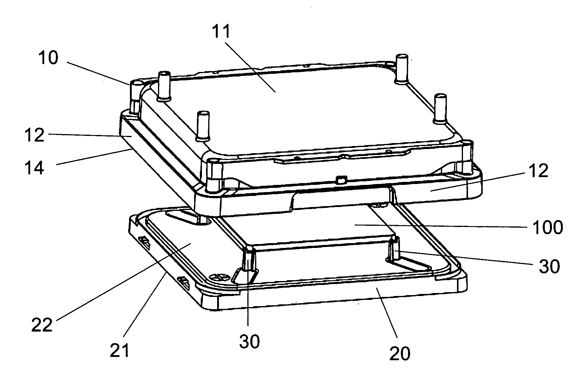
[0024]First, referring to FIG. 2, which is a view of thin-plate container of the present invention. The thin-plate container includes a container body 10 and a container door 20, the container body 10 having a top surface 11 and four side surfaces 12 neighboring to the top surface 11, the aforementioned top surface 11 and the four side surfaces 12 forming an interior area (not shown in Figure) and an opening 14; the container door 20 having an outer surface 21 and an inner surface 22, wherein the inner surface 22 is used for closing the opening 14 of the container body 10 and is respectively disposed with a supporting pillar 30 in each of its four corners for supporting a thin plate 100, the thin plate 100 being a reticle or...


PUM


Abstract

A thin-plate container comprises a container body with an opening and an interior area and being pivotally connected to at least a pair of swing hooks near its opening; a container door for closing the opening of the container body; and a latch component disposed in the container door, which is movable in a to-and-fro direction between a first position and a second position when the container door closes the opening of the container body, wherein in the first position, the latch component is contained in the container door, and in the second position, the latch component extends beyond the container door and is in contact with the pair of swing hooks of the container body for making the container door to move in a sealing direction by using the swing hooks to achieve a sealed status between the container door and the container body.

Description

BACKGROUND OF THE INVENTION[0001]1. Field of the Invention[0002]The present field of the invention is related to a thin-plate container, and more particularly, to a thin-plate container with high air tightness ability.[0003]2. Description of the Prior Art[0004]Currently in semiconductor fabrication plants, most storage devices of wafer and photomask use a standardized mechanical interface (SMIF) proposed by Hewlett-Packard Co., which has been disclosed in U.S. Pat. No. 4,532,970 and U.S. Pat. No. 4,534,389. The purpose of SMIF system is to ensure that during the transporting and storing process, gas surrounding wafer and reticle is basically static in relation to the wafer and reticle, and that particles in the ambient environment will not enter the space surrounding the wafer and reticle.[0005]Therefore a transport container used in SMIF system needs to be equipped with high air tightness ability to prevent gas or particles of the exterior environment from entering the transport co...

Claims


Application Information

Patent Timeline
Patent Type & Authority Applications(United States)
IPC IPC(8): H01L21/673
CPCH01L21/67353H01L21/67373H01L21/67359
Inventor CHENG, KUNG-HAOCHEN, CHANG-CHENG
Owner GUDENG PRECISION IND CO LTD
Why Eureka
Try Eureka