
Staggered light collectors for concentrator solar panels

Inactive Publication Date: 2010-05-27
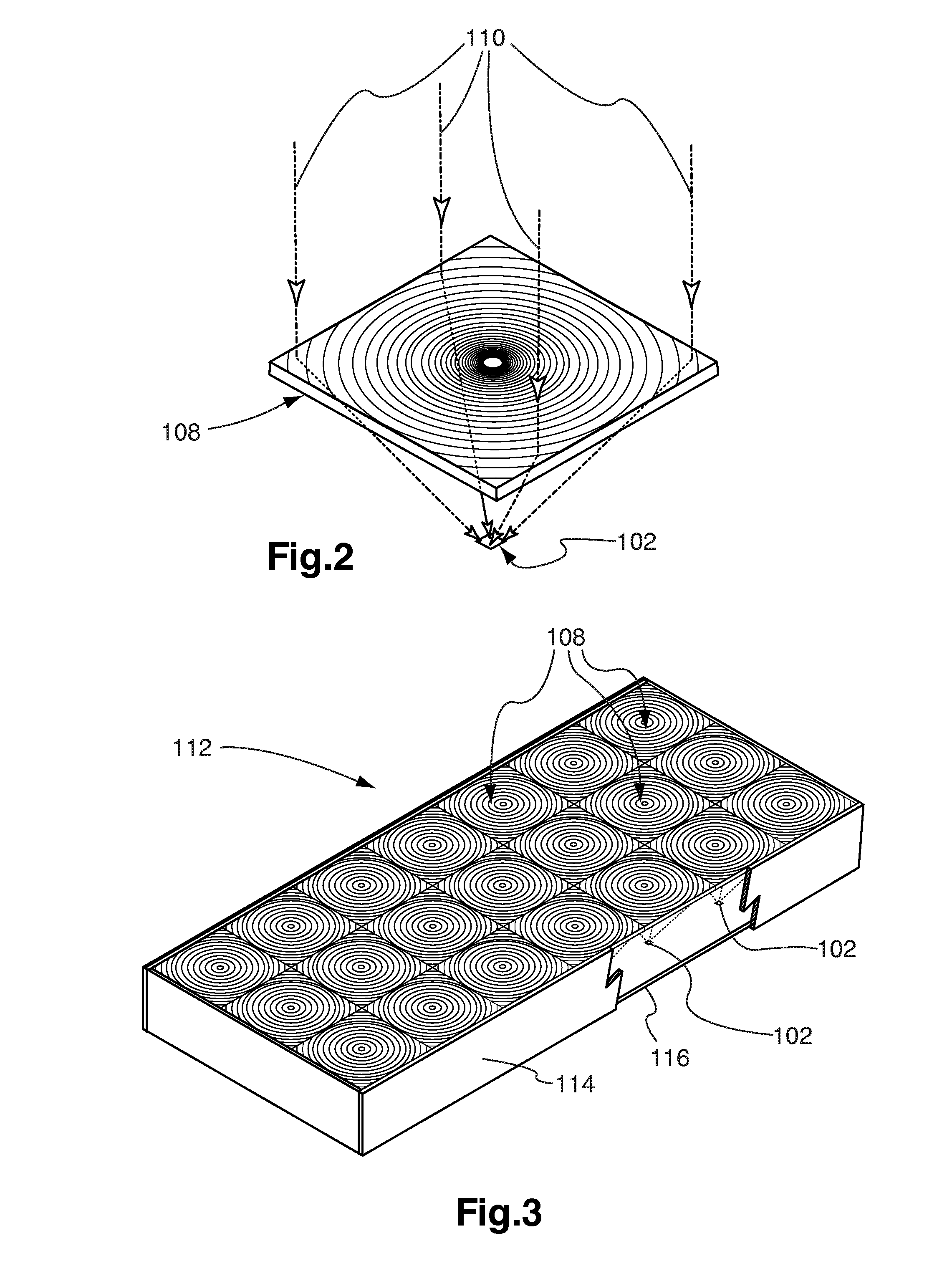
MORGAN SOLAR INC
View PDF3 Cites 61 Cited by
  • Summary
  • Abstract
  • Description
  • Claims
  • Application Information

AI Technical Summary

Benefits of technology

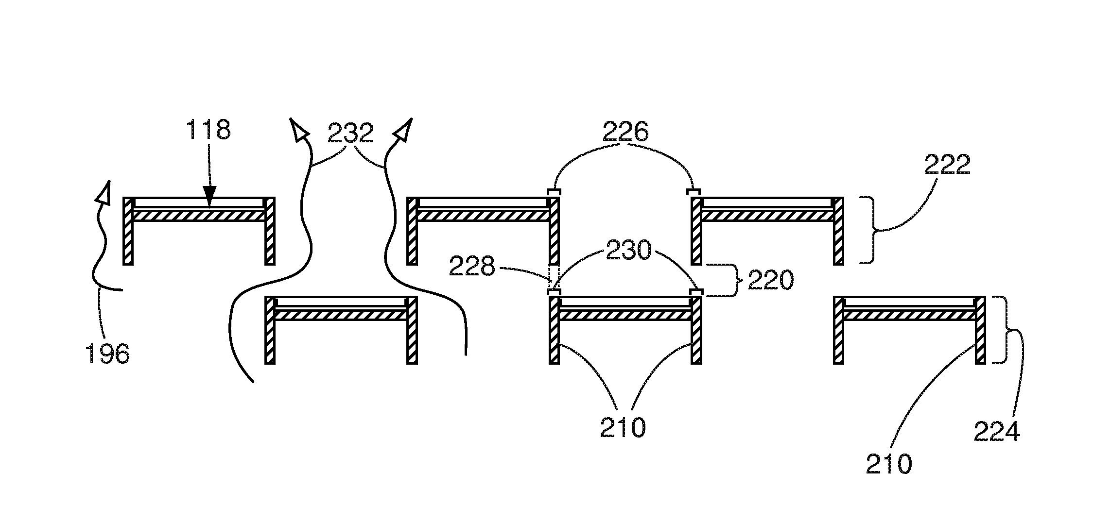
[0011]In a first aspect, there is provided a photovoltaic tracking solar energy capturing and conversion system. The system comprises a first group of spaced-apart solar energy collectors modules secured to a support. The system also comprises a second group of spaced-apart solar energy collectors modules secured to said support, each solar energy collector module of said first and second groups of solar energy collector modules including an array of photovoltaic cells associated with a respective optical light collector element, the first and second groups of solar energy collectors modules defining two substantially parallel planes separated by an air gap, said air gap dimensioned to ensure heat dissipation to prevent overheating of the photovoltaic cells, the first and second groups of solar energy collectors modules being staggered with respect to each other by an amount that allows the optical light collector elements of each solar energy collector module to be exposed to substantially equal levels of solar energy for capture by said optical light collector elements and associated photovoltaic cells, wherein the two parallel planes and the staggered positioning of the first and second groups of solar energy collector modules reduce wind load upon the solar energy collector modules. The system further comprises a tracking system that orients said support to maximize the amount of solar energy captured by said staggered rows of solar energy collector modules to provide an optimum exposure of each optical light collector element to the solar energy and further increase the heat dissipation at the photovoltaic cell level for each position of the solar energy collector modules as provided by the tracking system.
[0012]In a second aspect, there is provided a compact photovoltaic tracking solar energy capturing and conversion system. The system comprises a first group of solar energy collectors modules secured to a support and a second group of solar energy collectors modules secured to a support. Each solar energy collector module of said first and second groups of solar energy collector modules including an array of photovoltaic cells each associated with a respective light guide optical concentrator, each solar energy collector module of the first and second groups being spaced apart from an adjacent solar energy collector module of its respective group by a distance substantially equal to a width of an active area of the photovoltaic cell, plus the width of a mounting section, the first and second groups of solar energy collector modules defining two substantially parallel planes, the substantially parallel planes being separated by an air gap, wherein the solar energy collector modules of the first and second groups are staggered with respect to each other by an amount that provides substantial equal exposure to solar energy minus a shadowing area created by a lateral mounting portion of the photovoltaic cell to said support. The system further comprises a tracking system that orients said support to maximize the amount of solar energy captured by said staggered rows of solar energy collector modules to provide an optimum exposure of each optical light collector element to the solar energy and further increase the heat dissipation at the photovoltaic cell level for each position of the solar energy collector modules as provided by the tracking system.
[0013]In a third aspect, there is provided a method of dissipating heat accumulation in concentrated photovoltaic solar panels caused by an optic concentrator. The method comprises steps of providing a first group of solar energy collectors modules secured to a support and providing a second group of solar energy collectors modules secured to the support. Each collector module of said first and second groups of solar energy collector modules including an array of photovoltaic cells each associated with a respective optic concentrator, each solar energy collector module of the first and second groups of solar energy collector modules being spaced apart from another solar energy collector module of its respective group by a distance substantially equal to a width of an active area of a light capture area of a solar energy collector module, to create a heat dissipation pathway, said the first and second groups of solar energy collector modules defining substantially parallel planes separated by an air gap to create an additional heat dissipation pathway, wherein the solar energy collector modules from the first and second groups are staggered with respect to each other by an amount that provides substantially equal exposure to the solar energy minus a shadowing area created by a lateral mounting portion of the photovoltaic cell to said support. The method further comprises a step of providing a tracking system that orients said support to maximize the amount of solar energy captured by said staggered rows of solar energy collector modules to provide an optimum exposure of each optical light collector element to the solar energy and further increase the heat dissipation at the photovoltaic cell level for each position of the solar energy collector modules as provided by the tracking system.

Problems solved by technology

It does however present a large, flat wall to oncoming wind, which can put considerable force onto the tracker.
PV cell performance decreases as temperature increases, and excessive overheating can result in permanent damage to the modules, so effective heat shedding is required to make CPV work.
However, most systems employ passive cooling, wherein heat only leaves the system through irradiative and convective mechanisms into the surrounding air.
This results in a low degree of air circulation and can result in excessive heating of the system.
This has the detrimental consequence of reducing the area over which light can be gathered by the modules, diminishing overall efficiency.

Method used


Image

  • Staggered light collectors for concentrator solar panels
  • Staggered light collectors for concentrator solar panels
  • Staggered light collectors for concentrator solar panels

Examples


Embodiment Construction

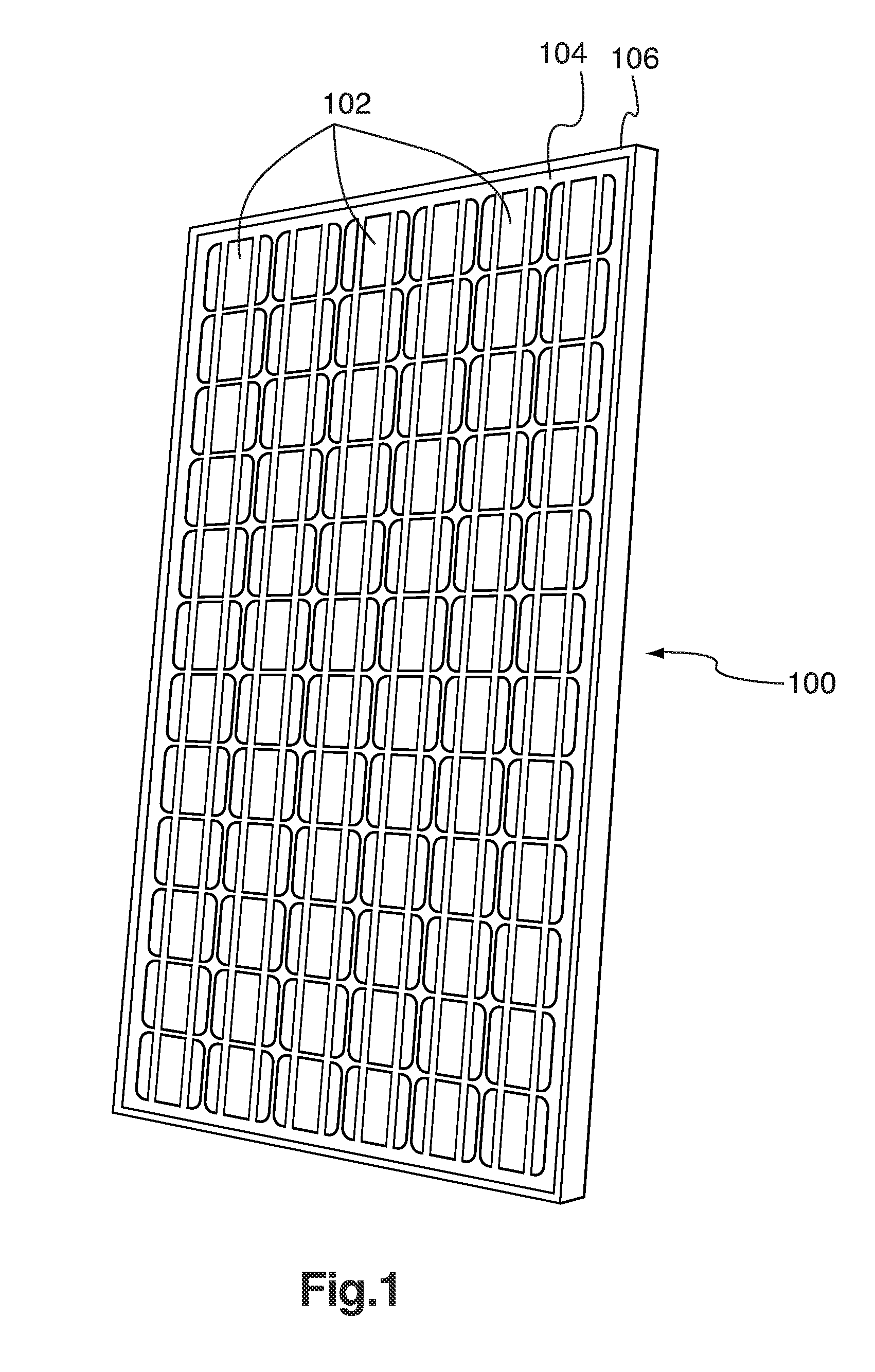
[0053]The present invention is related to an arrangement of solar energy collector modules (SECMs). A first group of spaced-apart SECMs defines a first plane which is substantially parallel to a second plane defined by a second group of spaced-apart SECMs The first and second planes are separated by an air gap, and the first and second groups of SECMs are staggered with respect to each other. The staggering of the first and second groups of SECMs allows for light not harvested by the first group to be harvested by the second row and provides a low dead-space characteristic for the arrangement of solar energy collector modules. The air gap between the first and second planes allows for improved heat dissipation in the modules and prevents overheating of photovoltaic elements comprised in the SECMs. Further, the air gap and the spacing between SECMs of a same group allows for low resistance to wind. The arrangement of SECMs can be secured to a tracking system to allow optimum solar en...


PUM


Abstract

A solar panel assembly with a first group of spaced-apart solar energy collector modules and a second group of spaced-apart solar energy collector modules. The first and second groups lie in respective parallel planes, which define an air gap therebetween, and are staggered with respect to each other. The staggering of the groups allows for light not harvested by the first row to be harvested by the second row and provides a low dead-space characteristic for the solar panel assembly. The gap between the planes and the space between individual solar energy collector modules of a same group allow for improved heat dissipation in the modules and for the solar panel assembly to offer low resistance to wind.

Description

CROSS REFERENCE TO RELATED APPLICATIONS[0001]This application claims the benefit of priority of U.S. Provisional Patent Application No. 61 / 094,168 filed Sep. 4, 2009, which is incorporated herein by reference in its entirety.FIELD OF THE INVENTION[0002]The present invention relates generally to solar power. More particularly, the present invention relates to reducing wind loading and improving heat dissipation for tracker mounted solar power systems, especially for concentrated photovoltaic systems.BACKGROUND OF THE INVENTION[0003]Concentrated photovoltaic (CPV) systems are known and currently produced by a number of companies around the world including Amonix, Concentrix, and Sol3g. The systems are based on the idea of making a solar module using an optic, such as a lens or mirror, to collect light over a large area and concentrate it onto small photovoltaic (PV) cells which then convert that light to electricity.[0004]The optics can be a Fresnel lens, a Cassegrain optic, a parabol...

Claims


Application Information

Patent Timeline
IPC IPC(8): H01L31/052F24S50/20
CPCF24J2/062F24J2/067F24J2/085F24J2/10F24J2/541H01L31/0547F24J2002/0084H01L31/052Y02E10/52H02S20/00H01L31/0543F24J2/542H02S20/32H02S40/22H01L31/042H02S40/425F24S2020/16F24S23/70F24S23/12F24S30/425F24S30/452F24S23/31F24S23/10
Inventor MORGAN, JOHN PAULMORGAN, ERIC ANDRES
Owner MORGAN SOLAR INC
Learn More