
Spin head, apparatus for treating substrate, and method for treating substrate

a technology for substrates and spin heads, applied in the direction of cleaning processes and apparatus, chemistry apparatus and processes, cleaning using liquids, etc., can solve problems such as product defects and product defects

Active Publication Date: 2010-05-27
SEMES CO LTD
View PDF5 Cites 316 Cited by
  • Summary
  • Abstract
  • Description
  • Claims
  • Application Information

AI Technical Summary

Benefits of technology

[0028]In other embodiments, a driven magnet may be installed at the rotation rod, a driving magnet may be disposed under the driven magnet, the driven magnet and the driving magnet may have identical poles facing each other, the chuck pin may move from the supporting position to the waiting position by moving the drivi

Problems solved by technology

When the chuck pins are moved to the waiting positions by centrifugal force during a process, it is difficult for the chuck pins to stably support the substrate, thus causing defects in products.
For this reason, it is difficult for the chuck pins to stably support the substrate, thus causing defects in products.

Method used


Image

  • Spin head, apparatus for treating substrate, and method for treating substrate
  • Spin head, apparatus for treating substrate, and method for treating substrate
  • Spin head, apparatus for treating substrate, and method for treating substrate

Examples


Embodiment Construction

[0054]Embodiments of the present disclosure will be described below in more detail with reference to the accompanying drawings. The present disclosure may, however, be embodied in different forms and should not be constructed as limited to the embodiments set forth herein. Rather, these embodiments are provided so that this disclosure will be thorough and complete, and will fully convey the scope of the present disclosure to those skilled in the art. Thus, the shapes of elements are exaggerated for clarity in the drawings.

[0055]An apparatus, cleaning a substrate W with chemical solution, rinse solution, and dry gas, will now be described according to an embodiment of present disclosure. However, the spirit and scope of the present disclosure is not limited thereto, and thus, a spin head according to an embodiment of the present disclosure may be applied to various devices rotating the substrate W to perform a process, such as an etch process.

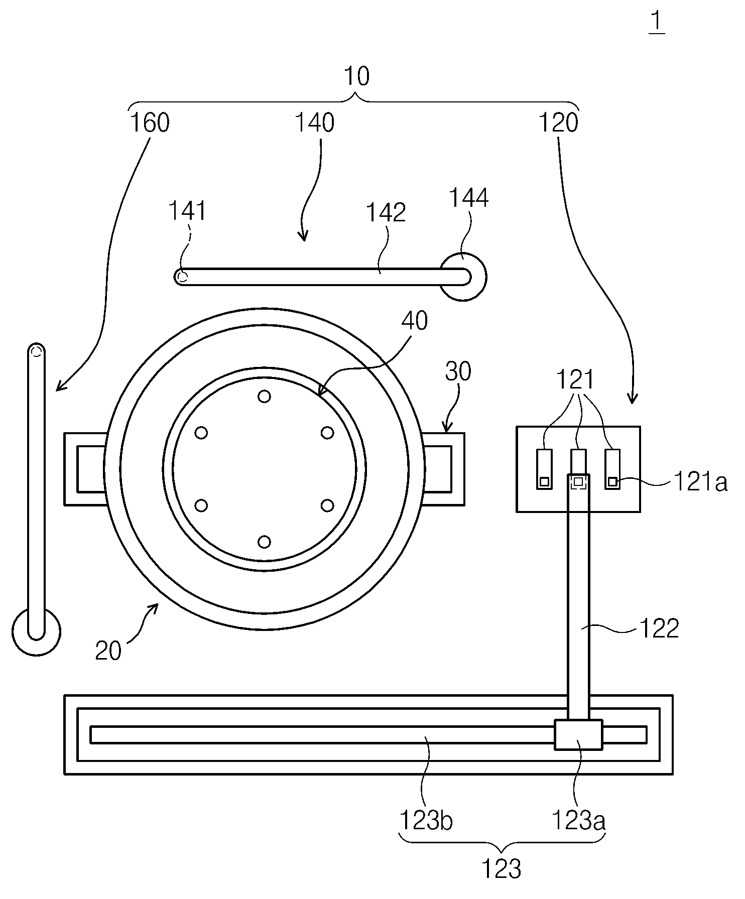
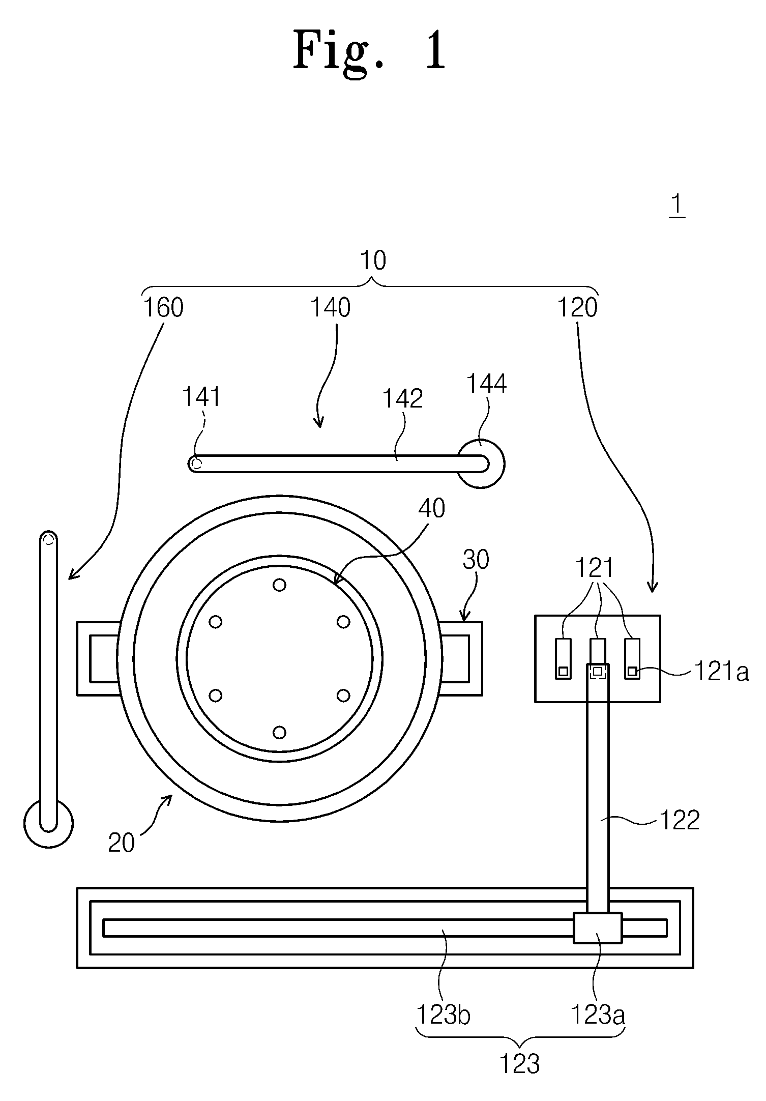
[0056]FIG. 1 is a plan view illustrating ...


PUM


Abstract

Provided is a spin head supporting a substrate and rotating the substrate. The spin head includes a body, chuck pins installed on the body and moving between supporting positions where a substrate is supported and waiting positions providing space for loading / unloading of the substrate, and a chuck pin moving unit configured to move the chuck pins. The chuck pin moving unit includes a rotation rod coupled with each of the chuck pins, a pivot pin fixing the rotation rod to the body, and a driving member rotating the rotation rod about the pivot pin as a rotation shaft to move the chuck pin from the supporting position to the waiting position. When the body rotates, the rotation rod uses reverse centrifugal force to apply force to the chuck pin from the waiting position to the supporting position. The chuck pins include first pins and second pins that alternately chuck a substrate during a process.

Description

CROSS-REFERENCE TO RELATED APPLICATIONS[0001]This U.S. non-provisional patent application claims priority under 35 U.S.C. §119 of Korean Patent Application Nos. 10-2008-0118168, filed on Nov. 26, 2008, 10-2008-0118164, filed on Nov. 26, 2008, and 10-2009-0035924, filed on Apr. 24, 2009, the entire contents of which are hereby incorporated by reference.BACKGROUND OF THE DISCLOSURE[0002]The present disclosure disclosed herein relates to an apparatus for treating a substrate and a method for treating a substrate, and more particularly, to a rotatable spin head supporting a substrate in a process such as a semiconductor process, and an apparatus and a method for treating the substrate using the spin head.[0003]A semiconductor process includes a process of etching or cleaning thin layers, foreign substances, and particles on a wafer. Such an etching or cleaning process is performed by placing a wafer on a spin head such that a surface of a pattern faces upward or downward, rotating the s...

Claims


Application Information

Patent Timeline
IPC IPC(8): B08B3/00
CPCH01L21/67051H01L21/68785H01L21/68728
Inventor LEE, TAEK YOUBBAE, JEONG YONGKIM, CHOON SIK
Owner SEMES CO LTD
Learn More