
Optical sheet, illuminating device and liquid crystal display device

a technology of illumination device and optical sheet, which is applied in the direction of optical elements, lighting and heating apparatus, instruments, etc., can solve the problems of insufficient contribution to an image brightness improvement, and achieve the effect of less power consumption and sufficient brightness

Inactive Publication Date: 2010-05-20
HITACHT MAXELL LTD
View PDF9 Cites 21 Cited by
  • Summary
  • Abstract
  • Description
  • Claims
  • Application Information

AI Technical Summary

Benefits of technology

[0014]The present invention has been made in consideration of the above-mentioned problems, and an object of the present invention is therefore to provide a prism sheet which may increase a degree of polarization (that is, increase a ration of the p-polarized light components) of the light output from the light guide plate, and to provide an illuminating device which may output illuminating light containing linearly polarized light components of high light intensity. Another object of the present invention is to realize a liquid crystal display device, which may provide a sufficient brightness but requires less power consumption, by using the above-mentioned illuminating device.
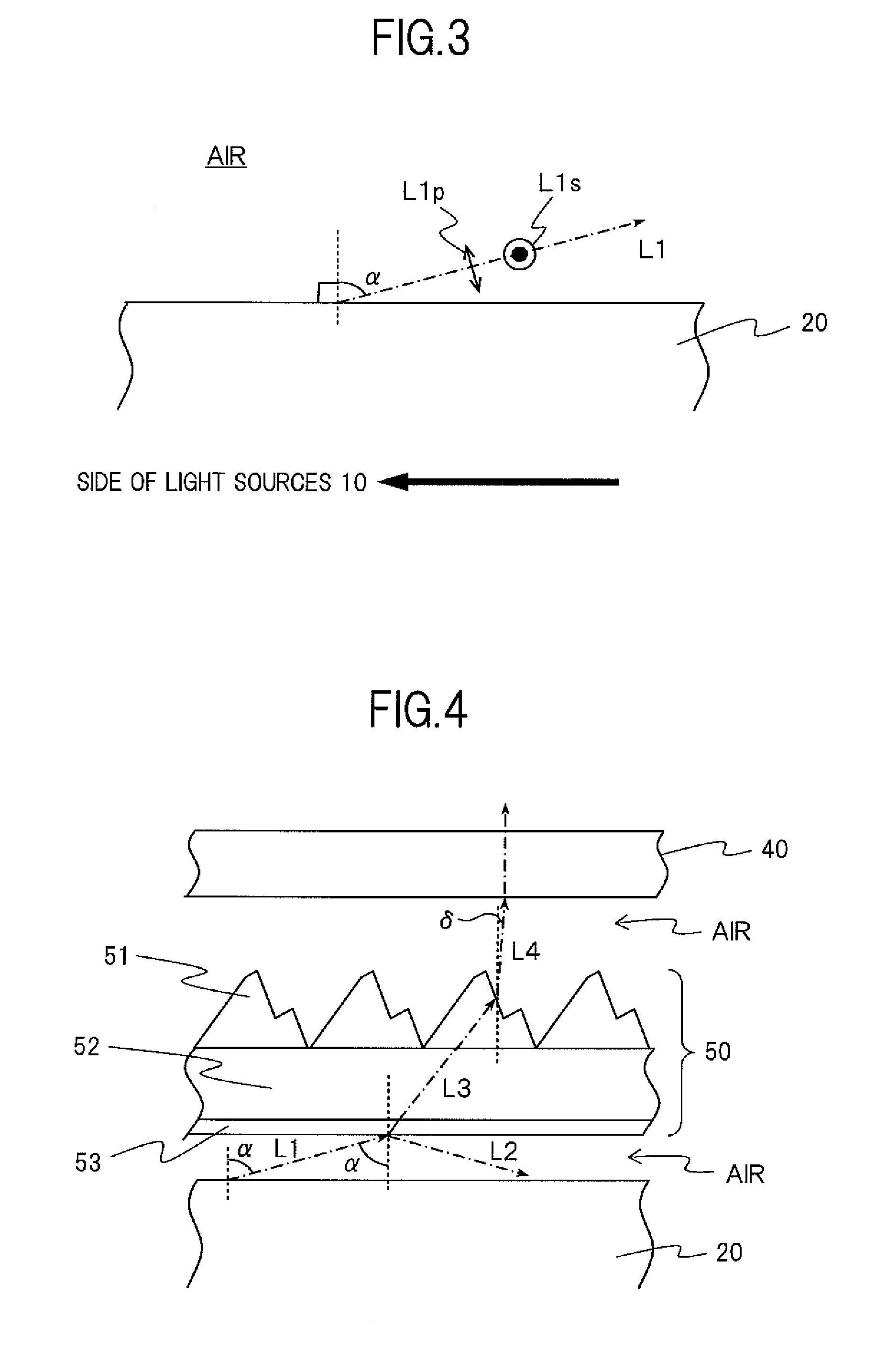
[0019]s-polarization high reflecting means provided on a surface opposite to the surface on which the prism arrays are formed, for increasing a ratio of p-polarized light components of light which is transmitted through the optical sheet by increasing a reflection of s-polarized light components with respect to light which enters the opposite surface at a predetermined angle.
[0034]in which a surface of the optical sheet on a side of the light guide plate includes s-polarization high reflecting means for increasing a ratio of p-polarized light components of light which is transmitted through the optical sheet by increasing a reflection of s-polarized light components with respect to the light which is output from the light guide plate and travels in a direction with a predetermined angle with respect to the front surface of the light guide plate.
[0058]in which a surface of the optical sheet on a side of the light guide plate includes s-polarization high reflecting means for increasing a ratio of p-polarized light components of light which is transmitted through the optical sheet, by increasing a reflection of s-polarized light components with respect to the light which is output from the light guide plate and travels in a direction at a predetermined angle with respect to the front surface of the light guide plate, and
[0071]According to the present invention, an illuminating device which emits illuminating light with a highlight intensity of linearly polarized light components may be realized. Further, by using the illuminating device, a liquid crystal display device which may provide sufficient brightness but requires less power consumption may be realized.

Problems solved by technology

However, the conventional technique is merely an attempt to output the light containing relatively more p-polarized light components in the front direction, and there is no consideration on increasing an absolute light intensity of the p-polarized light.
Therefore, there is a problem that the above-mentioned technique fails to sufficiently contribute to an improvement of brightness of an image when applied to a backlight of the liquid crystal display device.

Method used


Image

  • Optical sheet, illuminating device and liquid crystal display device
  • Optical sheet, illuminating device and liquid crystal display device
  • Optical sheet, illuminating device and liquid crystal display device

Examples


Embodiment Construction

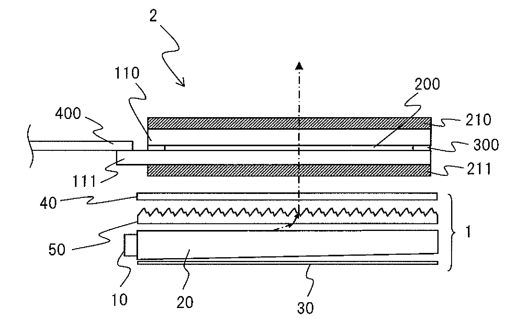
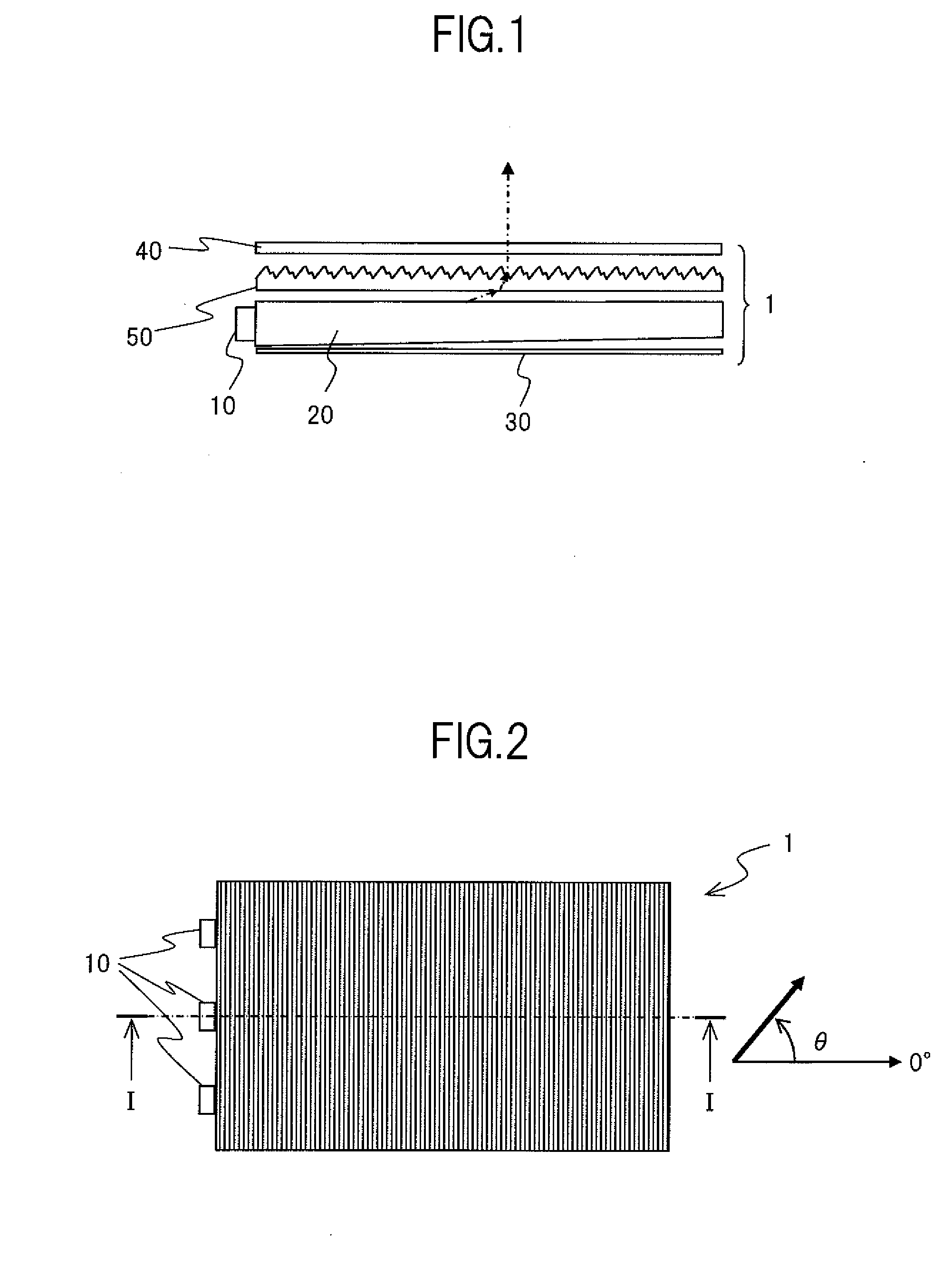
[0092]A main configuration of an illuminating device according to an exemplary embodiment of the present invention is schematically described below. The illuminating device according to the exemplary embodiment includes at least a light source, a light guide plate which has one end surface (side surface) placed adjacent to the light source and outputs light coming from the end surface from a front surface (light outputting surface) of the light guide plate, an optical sheet (hereinafter also referred to as prism sheet) including prism arrays each having at least two inclined surfaces and ridge line extending in one direction (a direction along the end surface of the light guide plate from which light enters), and a reflection sheet.

[0093]The main configuration of the illuminating device according to the exemplary embodiment is as follows.

[0094](Configuration 1) A light guide plate is used, in which an output angle of light, which is output from the light outputting surface of the li...


PUM


Abstract

An illuminating device includes: a light guide plate for outputting light, which enters the light guide plate from one side surface, from a front surface of the light guide plate; an optical sheet disposed on the front surface of the light guide plate; and a reflection sheet disposed on a rear surface of the light guide plate. The optical sheet includes prism arrays which are provided on a surface of the optical sheet opposite to the light guide plate, and each of which has at least two inclined surfaces and a ridge line extending in one direction. The light guide plate changes a polarization state of light that is reflected by the surface of the optical sheet, is transmitted through the light guide plate, is reflected by the reflection sheet, is transmitted through the light guide plate again, and then enters the optical sheet.

Description

CROSS-REFERENCE TO RELATED APPLICATION[0001]The present application claims priority from Japanese application JP2008-297281 filed on Nov. 20, 2008, the content of which is hereby incorporated by reference into this application.BACKGROUND OF THE INVENTION[0002]1. Field of the Invention[0003]The present invention relates to an illuminating device which functions as a planar light source, an optical sheet which is used in the illuminating device, and a liquid crystal display device which includes the illuminating device as a backlight.[0004]2. Description of the Related Art[0005]A display device is one of media for visually conveying information to people. In the recently advanced information society, the display device has become a material tool for people as well as the society. Specifically, a recent liquid crystal display device is dramatically improved in its performance and is employed as a display device for a cell-phone, a personal computer, a big screen TV, or the like. The ty...

Claims


Application Information

Patent Timeline
IPC IPC(8): G02F1/1335F21V7/04F21V7/22
CPCF21V7/04F21V7/22G02B6/0053G02F2001/133607G02F1/133615G02F1/13362G02B6/0056F21V7/24G02F1/133607G02B5/04G02F1/1335
Inventor ADACHI, MASAYASUGITA, TATSUYAARAKI, CHIEKO
Owner HITACHT MAXELL LTD
Learn More