
Two-phase expansion system and method for energy recovery

Active Publication Date: 2010-05-20
AI ALPINE US BIDCO INC
View PDF3 Cites 21 Cited by
  • Summary
  • Abstract
  • Description
  • Claims
  • Application Information

AI Technical Summary

Problems solved by technology

This volume ratio is problematic for all types of turbomachinery.
Practically, the volume ratio (and hence pressure ratio) must be limited along with the work output.
These constraints lower the thermodynamic efficiency when dealing with higher temperature waste heat.

Method used


Image

  • Two-phase expansion system and method for energy recovery
  • Two-phase expansion system and method for energy recovery
  • Two-phase expansion system and method for energy recovery

Examples


example

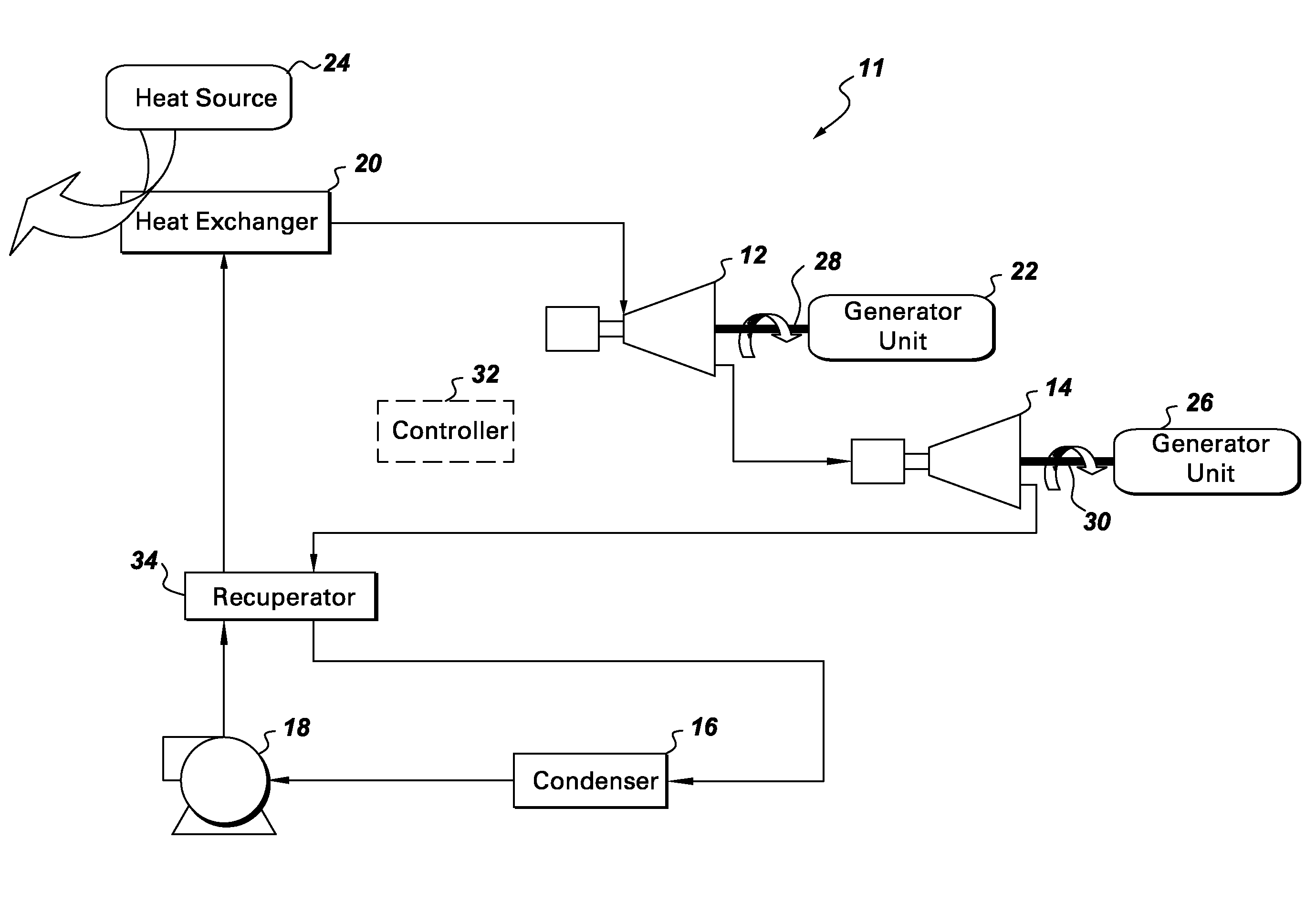
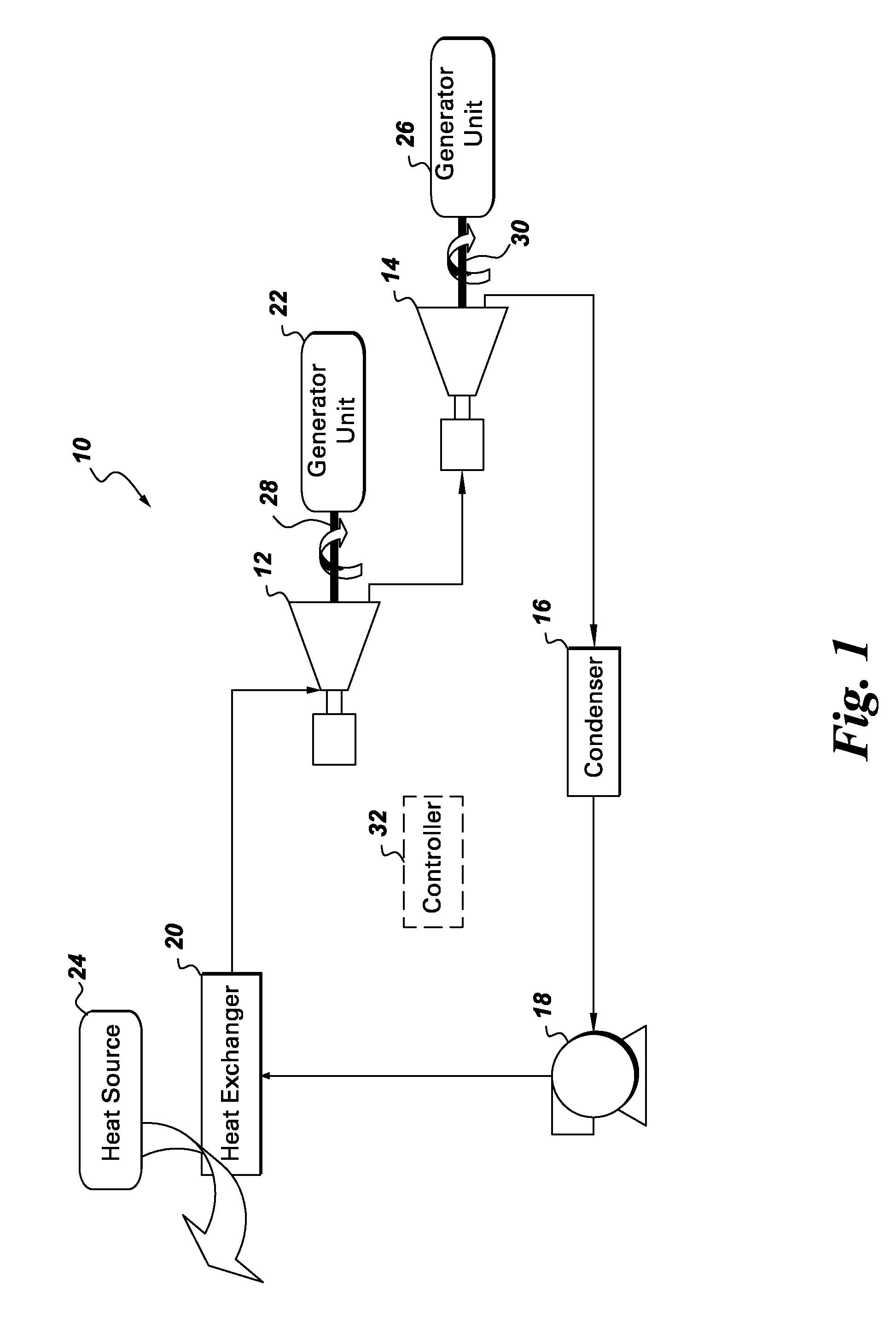
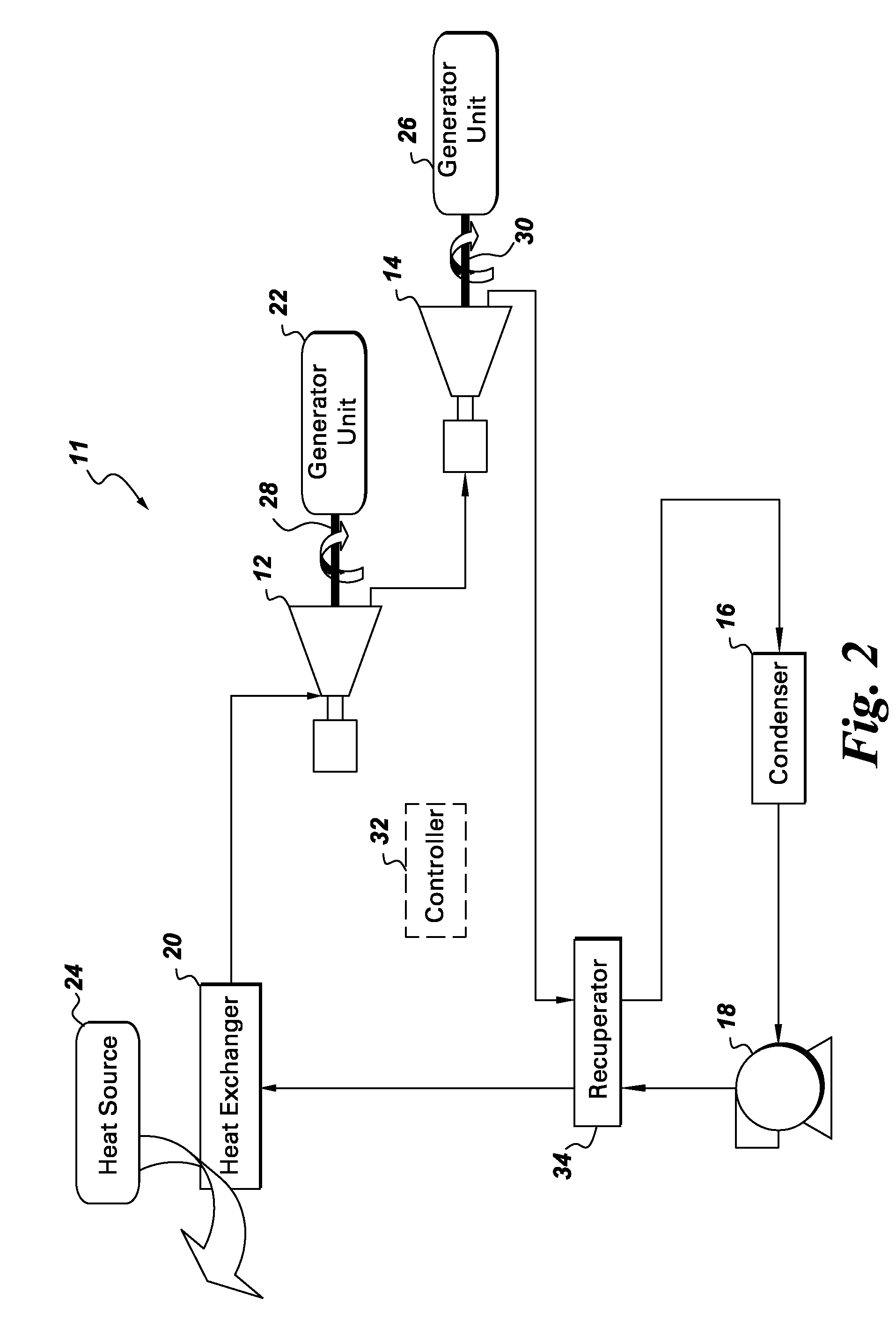
[0022]In one specific example, for purposes of illustration only, water is used as the working fluid, heat source 20 includes exhaust gas at about 530 degrees Celsius, heat exchanger uses the heat from the exhaust gas to heat the working fluid from an input temperature of about 145 degrees Celsius to an output temperature of about 180 degrees Celsius, radial inflow expander 12 has operating parameters of power at about 5600 kilowatts, mass flow at about 121 kilograms per second, inlet pressure at about 130 bars, temperature at about 245 degrees Celsius, and vapor quality (evaporation rate) of about 29%, screw expander 14 has operating parameters of power at about 11800 kilowatts, outlet pressure at about 4 bars or 5 bars, temperature at about 148 degrees Celsius, and vapor quality (evaporation rate) of about 40%, the condensation temperature in condenser 16 is about 15 degrees Celsius, and the pump has operating parameters of power at about 1350 kilowatts, temperature of about 145 d...


PUM


Abstract

A closed loop expansion system for energy recovery includes a heat exchanger for using heat from a heat source to heat a working fluid of the closed loop expansion system to a temperature below the vaporization point of the working fluid; a radial inflow expander for receiving the working fluid from the heat exchanger and for expanding and partially vaporizing the working fluid; a screw expander for receiving the working fluid from the radial inflow turbine and for further expanding and vaporizing the working fluid; and a condenser for receiving the working fluid from the screw expander and for liquefying the working fluid.

Description

BACKGROUND[0001]The subject matter disclosed herein relates generally to energy recovery systems.[0002]In many closed loop expansion systems, a working fluid is heated to a temperature above its boiling point before being expanded to extract energy (work). A trilateral flash cycle, in contrast, is a thermodynamic cycle for extracting work from a heat source wherein the working fluid is heated to a temperature below its boiling point before being provided to a turbine (expander) to extract energy. During expansion, a large portion of the fluid (10-100%) typically flashes to a vapor state, causing a very large volume ratio (of volume flow per second at the exit over volume flow per second at the inlet). This volume ratio is problematic for all types of turbomachinery. Practically, the volume ratio (and hence pressure ratio) must be limited along with the work output. These constraints lower the thermodynamic efficiency when dealing with higher temperature waste heat.[0003]It would be ...

Claims


Application Information

Patent Timeline
IPC IPC(8): F01K25/08
CPCF22B3/04F01K23/10
Inventor AST, GABORFREY, THOMAS JOHANNESKOPECEK, HERBERTBARTLETT, MICHAEL ADAMHUCK, PIERRE SEBASTIEN
Owner AI ALPINE US BIDCO INC
Learn More