
Surgical instrument to measure an intervertebral space

a technology of intervertebral space and surgical instruments, which is applied in the field of medical devices, can solve the problems of occupying a large part of surgery time and necessitating unnecessary mechanical loads on the patient's spinal column

Inactive Publication Date: 2010-05-06
WEBER HELMUT
View PDF6 Cites 43 Cited by
  • Summary
  • Abstract
  • Description
  • Claims
  • Application Information

AI Technical Summary

Benefits of technology

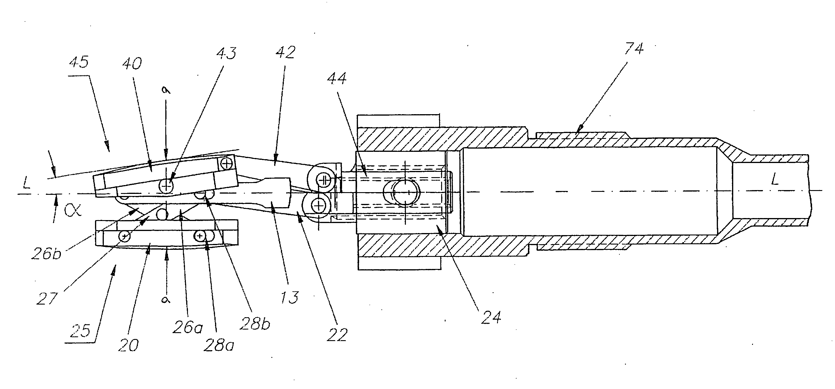
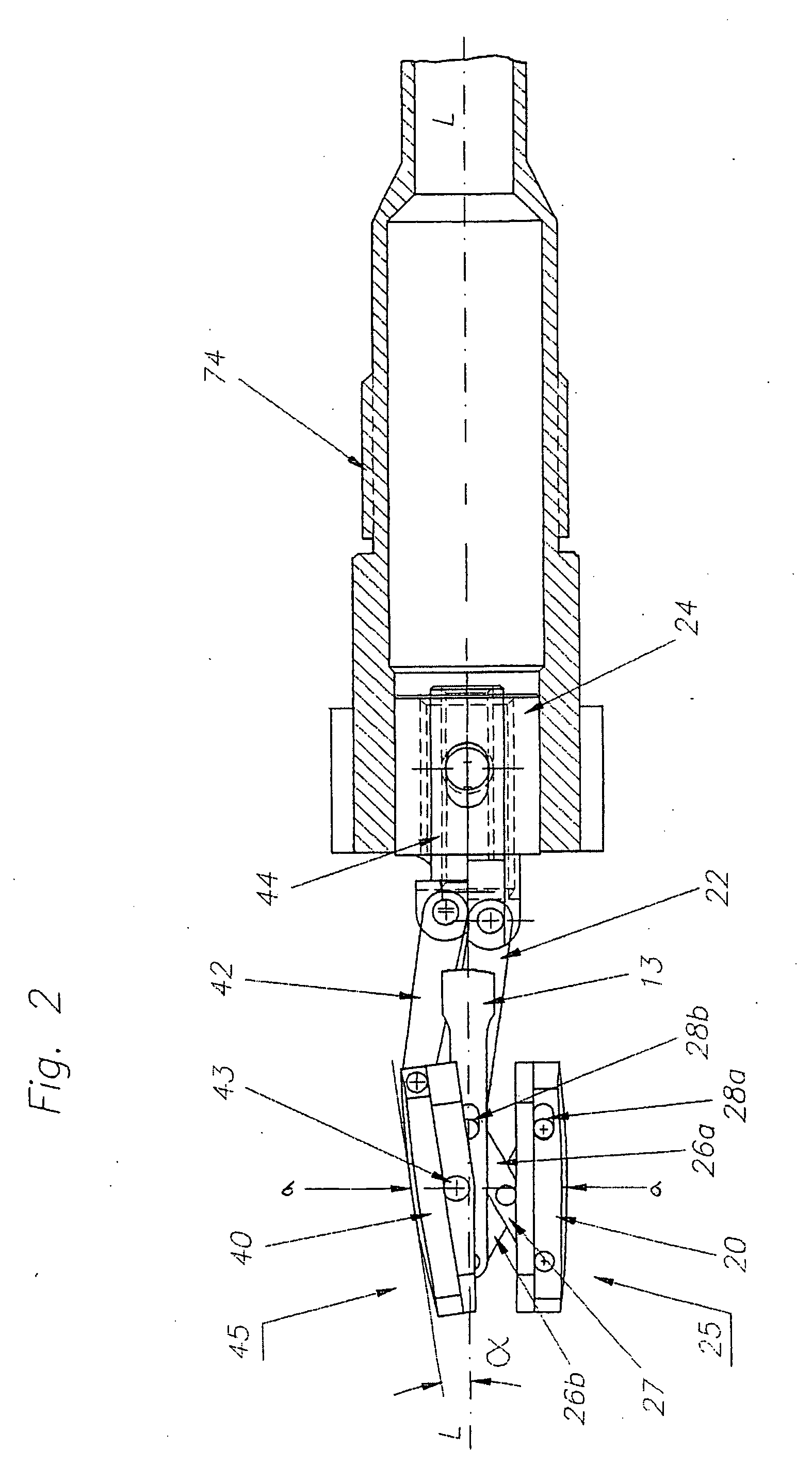
[0013]The advantage of the present invention is that owing to both the interval and enclosed angle being adjustable, only one spreading procedure is necessary to insert the surgical instrument; with it, due to the adjustability of the interval and the angle enclosed by the measurement plates, an in situ variation of the size is possible, so that through a one-time insertion of the surgical instrument, the exact fit of various implant dimensions can be checked and then immediately an intervertebral prosthesis with the correct dimensions can be inserted.
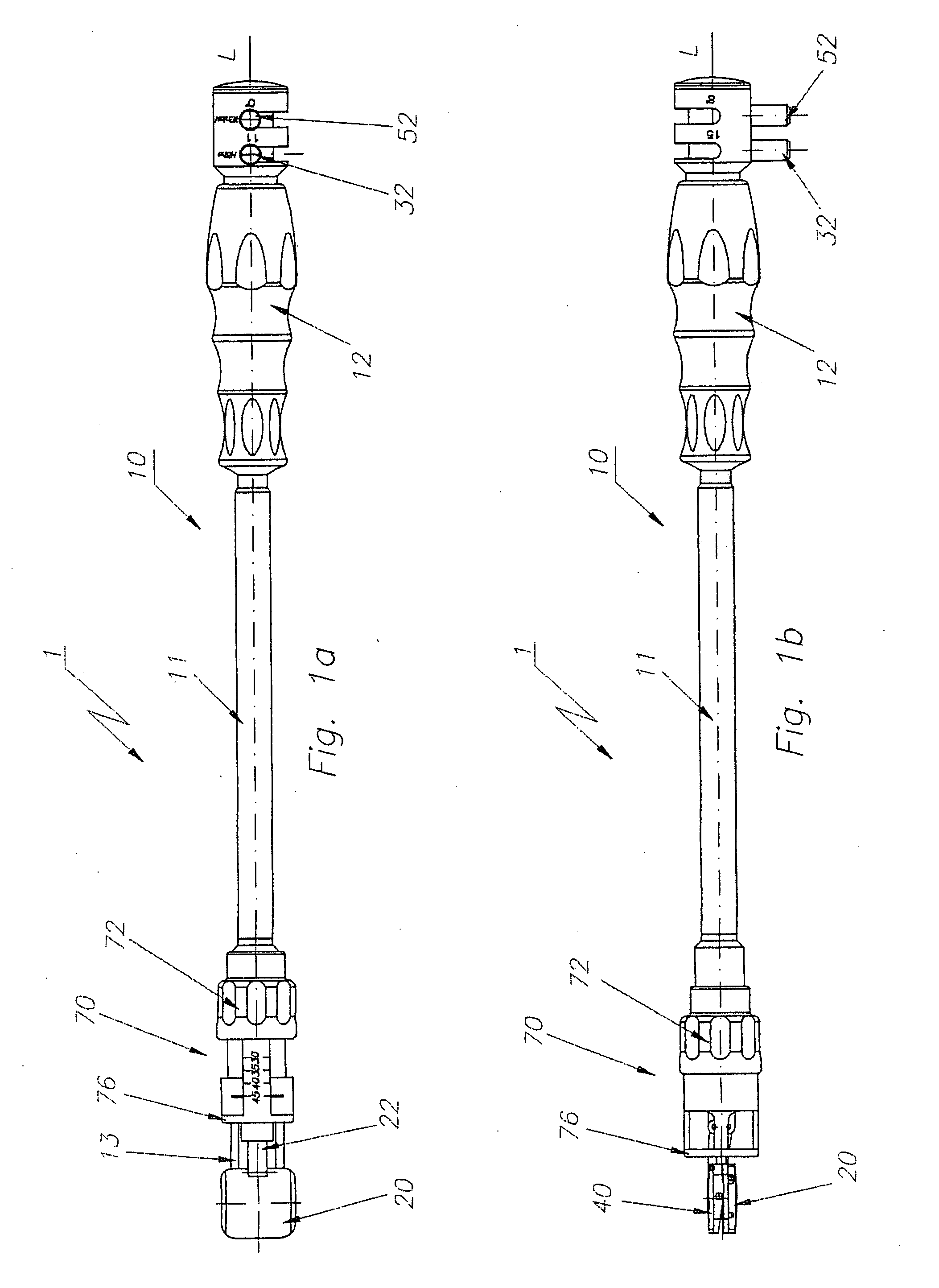
[0014]It is advantageous if, simultaneous with the implant dimensions, it is also possible to determine the depth at which the implant is placed, proceeding from the anterior side of the vertebral body via a movable deep stop. Such a deep stop can, for example, be determined by means of a cover surrounding the handle, which can for example be implemented by a cylindrical cover that can be screwed via an outer thread. The advantage of a cylindrical cover that surrounds the entire handle, is that only a single stop is present, and thus with a single adjustment the stop can be determined simultaneously for the two vertebral bodies between which the intervertebral prosthesis is to be mounted.
[0015]For a mechanical implementation of the surgical instrument, it is advantageous if a first measurement plate is configured for adjusting the distance and a second measurement plate is configured for setting the angle enclosed between the measurement plates. The mechanical implementation in this case is unique, so that for the one plate, all that must be provided is a mechanism for height adjustment; and, for the other plate, a mechanism to adjust the plate angle.
[0016]A height adjustment can be effected for example with a spreader that can be configured like an accordion lift table. With this it is advantageous that such a spreader execute a parallel adjustment of the measurement plate without any additional tipping.
[0017]Preferably, such a spreader has two scissors-like members able to move relative to each other, of which one can be controlled using a coupling rod, whereby the other is pivoted by means of an axle.
[0018]Linear motion of the coupling rod can be generated with especial ease from a threaded rod's rotational motion via a threaded bushing, which is placed in the handle so as not to turn. Owing to such guidance it is possible with particular ease to precisely adjust small motion steps of the one scissors-like part via a thread with a small passage height. This can be done, for example, using a threaded rod that is placed in the handle. On a proximal end of such a threaded rod, then, for example, an operating lever or an appropriately configured rotary knob can be placed. The advantage of using a threaded rod to operate it is that through selection of the threading, a reduction can be attained simply for the adjustment path.

Problems solved by technology

On the one hand, this takes up a large part of the time for surgery; and, on the other hand, it necessitates unnecessary mechanical loads on the patient's spinal column.

Method used


Image

  • Surgical instrument to measure an intervertebral space
  • Surgical instrument to measure an intervertebral space
  • Surgical instrument to measure an intervertebral space

Examples


Embodiment Construction

[0034]Reference will now be made in detail to several embodiments of the invention that are illustrated in the accompanying drawings. Wherever possible, same or similar reference numerals are used in the drawings and the description to refer to the same or like parts or steps. The drawings are in simplified form and are not to precise scale. For purposes of convenience and clarity only, directional terms, such as top, bottom, up, down, over, above, and below may be used with respect to the drawings. These and similar directional terms should not be construed to limit the scope of the invention in any manner. The words “connect,”“couple,” and similar terms with their inflectional morphemes do not necessarily denote direct and immediate connections, but also include connections through mediate elements or devices.

[0035]FIG. 1a shows a top view of an invention-specific surgical instrument 1 for measuring an intervertebral space. The surgical instrument 1 has a handle 10 that consists o...


PUM


Abstract

The invention is a surgical instrument for measuring an intervertebral space. On the distal end of a handle of the instrument there are at least two measurement plates, whereby an interval between the measurement plates, and an angle enclosed by the measurement plates, are adjustable.

Description

CROSS REFERENCE TO RELATED APPLICATIONS[0001]This application claims priority from European Patent Application No. 08 007 694.6, filed Apr. 21, 2008, the entire contents of which are herein incorporated fully by reference.FIGURE FOR PUBLICATION[0002]FIG. 2.BACKGROUND OF THE INVENTION[0003]1. Field of the Invention[0004]The present invention relates to a medical device for measuring spatial relationships between anatomical structures. More specifically, the present invention relates to a surgical instrument for measuring an intervertebral space in a precise manner so as to allow for optimal restoration of a damaged area.[0005]2. Description of the Related Art[0006]In prosthetics for intervertebral disks, it is customary to use so-called intervertebral prostheses as disk replacements. Such intervertebral prostheses are inserted between the vertebral bodies as part of an operation, replacing the defective disks removed earlier. To ensure that the original mobility and function of the s...

Claims


Application Information

Patent Timeline
Patent Type & Authority Applications(United States)
IPC IPC(8): A61B17/58
CPCA61F2/442A61F2002/4668A61F2002/4658A61F2/4657
Inventor WEBER, HELMUT
Owner WEBER HELMUT
Learn More