
Electrically propelled display device with simulated hovering and/or flying patterns

a display device and electric motor technology, applied in toys, entertainment, etc., can solve the problems of rotors periodically and frequently reversing their rotation directions, angular movement in this device, and the inability to maintain the hovering effect for a long time, etc., to achieve economic and convenient use

Inactive Publication Date: 2010-05-06
REYES CESAR AUGUSTO
View PDF8 Cites 7 Cited by
  • Summary
  • Abstract
  • Description
  • Claims
  • Application Information

AI Technical Summary

Benefits of technology

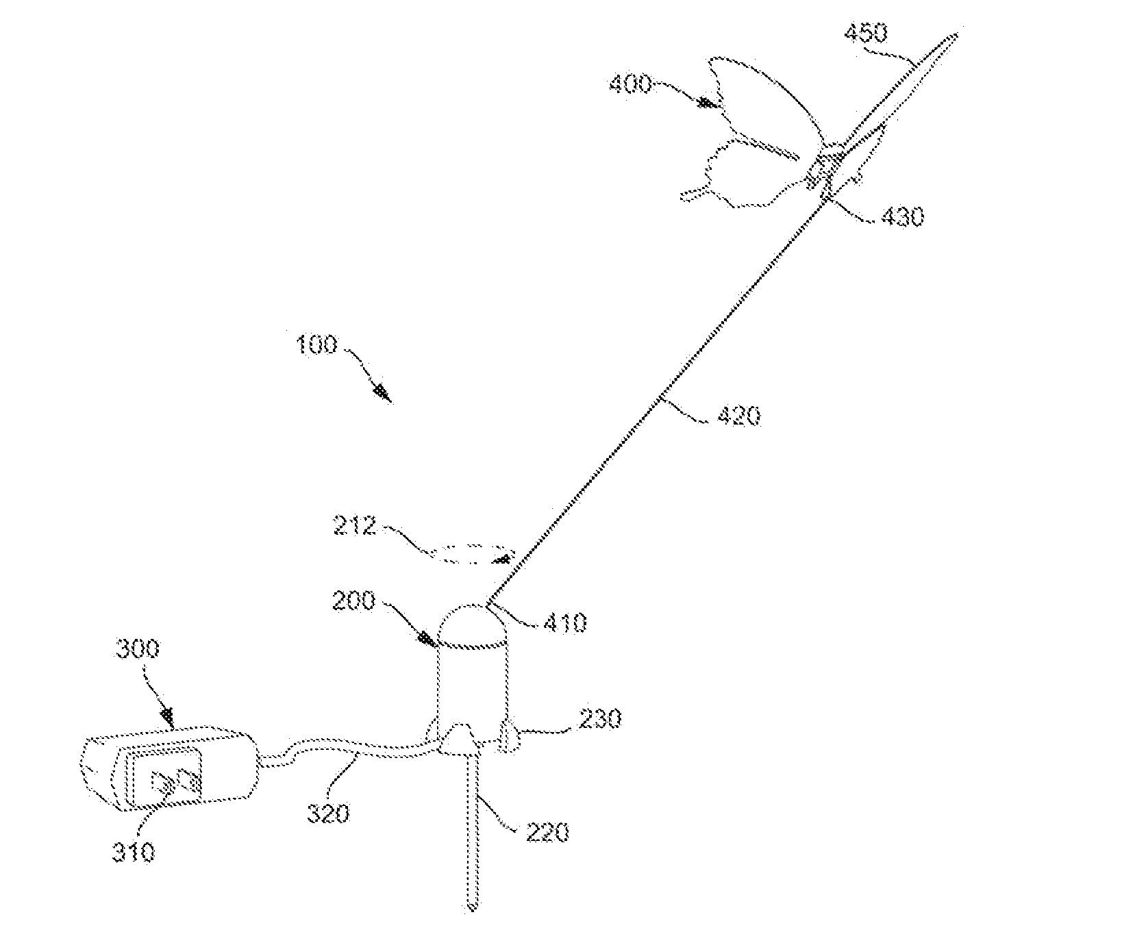
[0013]The general purpose of this present invention is to provide a very economical and easy to use product, that may be used in decorative, promotional, educational, and entertainment applications, and that succeeds in closely imitating the natural movement of aliforms, such as a butterfly, a dragonfly, a bird, a bat or a fairy. Just as an example, a butterfly pattern, with the aspect and movement of a real butterfly, may be very attractive for decorating a garden, the windows of a local shop, or simply a home.
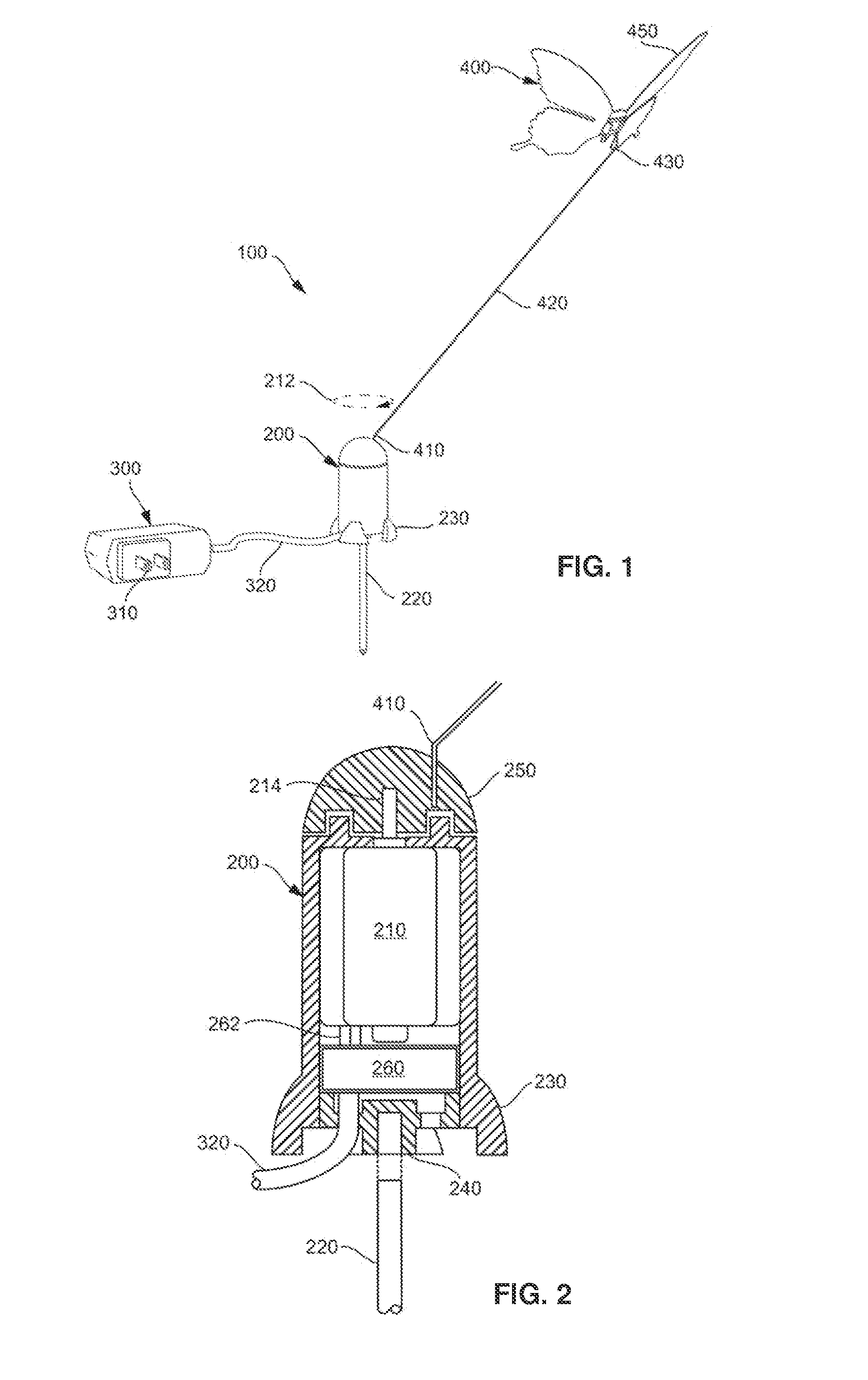
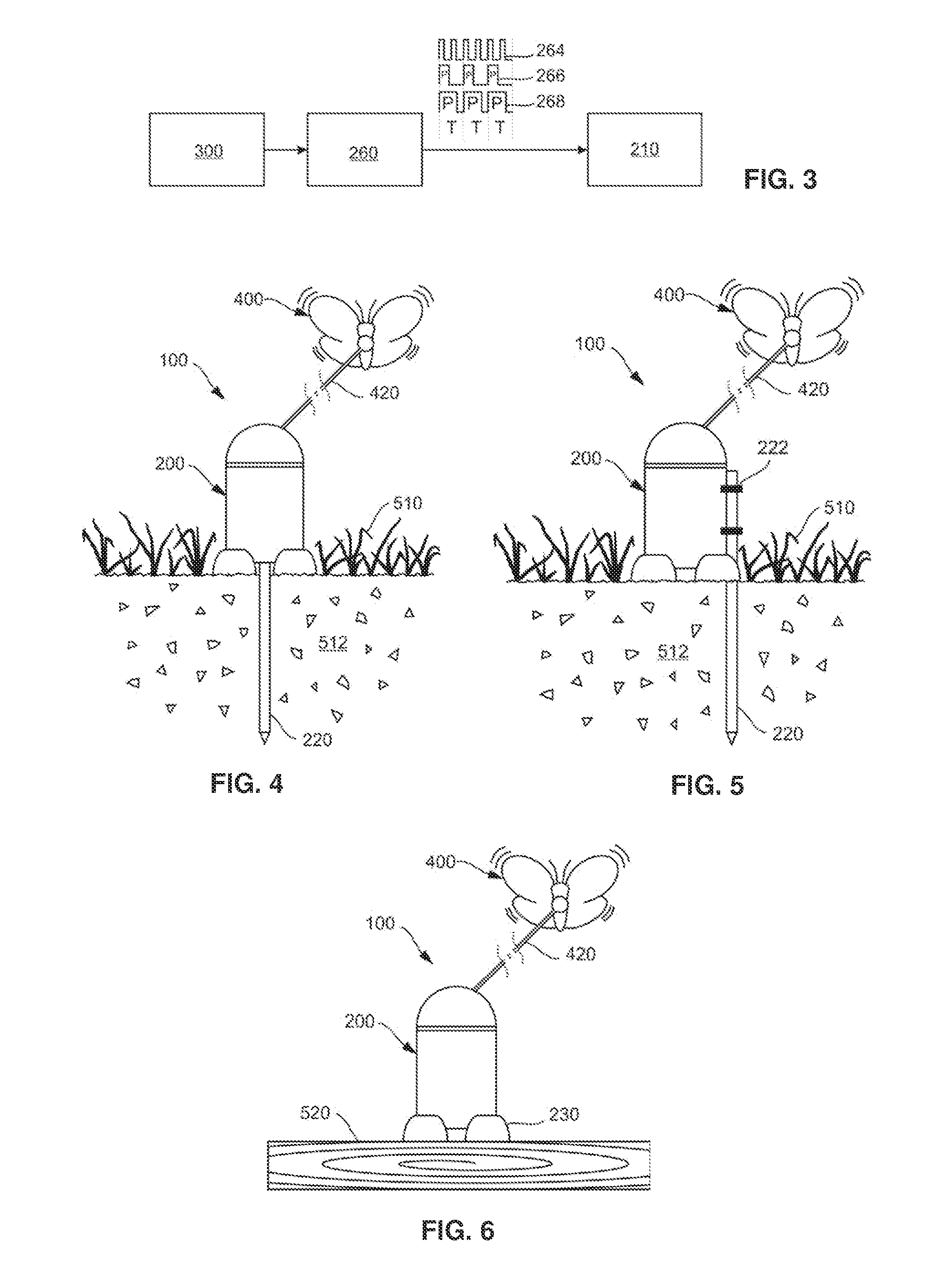
[0016]Yet another aspect of the purposed invention comprises an electronic circuit known as an oscillator connected to the motor. This circuit is responsible for generating a squared wave with a graduated frequency and pulse width according to the speed and intensity of the flapping movement that is desired for the flying object. Each pulse activates the motor for a time that lasts as long as the pulse. A series of short, consecutive pulses causes a series of short activations of the motor. When the wave frequency is higher, the pulses have a shorter duration, and, thus, the duration of activations of the motor is shorter. Visually, an effect similar to a vibration is produced. The variation of the relationship between the motor activating and shutting off from the wave may produce various oscillation effects in the motor shaft, such as, alterations in the rotational speed, or changes in the intensity of the object's flapping movement.

Problems solved by technology

But this hovering effect cannot be maintained for a long time, and it is just an effect that lasts few minutes.
However, the angular movement in this device is an irregular movement caused by the loose connections and the type of flippable holding member to which a steel spring is attached.
However, a predetermined mechanical load imposed on the permanent magnet rotor effected by random striking of the simulated butterfly against the plant, or by random horizontal and vertical excursions of the simulated butterfly in its orbital path, or by random “hand-up” of the permanent magnet rotor on its shaft, causes the rotor to periodically and frequently reverse its direction of rotation.

Method used


Image

  • Electrically propelled display device with simulated hovering and/or flying patterns
  • Electrically propelled display device with simulated hovering and/or flying patterns
  • Electrically propelled display device with simulated hovering and/or flying patterns

Examples


Embodiment Construction

[0032]Shown throughout the Figures, the invention is directed to an electrically propelled display device 100 with simulated hovering patterns, comprising a driving unit 200. Said driving unit includes a base 230, a central hollow body and a rotatable head 250. A power source 300 is connected to the driving unit 200 and a flexible support 420 is attached to the rotatable head 250 of the driving unit 200 and to a display pattern 400 as well. Said driving unit 200 includes in the central hollow body an oscillator electronic circuit 260 and an electric motor 210. Said oscillator electronic circuit 260 is connected to the power source 300 through a cable 320 and to the electric motor 210, and said electric motor 210 includes a driving motor shaft 214 attached to the rotatable head 250.

[0033]FIG. 1 illustrates the display device for simulation of flying objects 100 of the present invention. As shown, the system 100 comprises a power source 300, which in this case is an AC / DC adapter conn...


PUM


Abstract

The present invention is referred to an electrically propelled display device with simulated hovering and / or flying patterns, comprising a driving unit; said driving unit includes a base, a central hollow body and a rotatable head. A power source is connected to the driving unit, a flexible support is attached to the rotatable head of the driving unit and a display pattern is attached to the flexible support. Said driving unit includes in the central hollow body an oscillator electronic circuit and an electric motor. Said oscillator electronic circuit is connected to the power source and to the electric motor which includes a driving motor shaft attached to the rotatable head. This device simulates the movement of some flying objects and aliforms, such as birds, bats, butterflies, dragonflies, fairies, or the like. The oscillator circuit sends pulses at a certain frequency to the motor, generating an intermittent, rotational movement. This movement is transferred to the wire, which, then accentuates and transmits this movement to the object. The ultimate effect is the combination of a rotational movement, and a movement that simulates the flapping of wings of some flying animals and fairies, or the movement of other aquatic or terrestrial animals. The speed and intensity of rotation and flapping change with the frequency and pulse width of the wave that the oscillator sends. The device may be used in decorative, educational, promotional, and entertainment applications. It may be used both, indoors and outdoors.

Description

CROSS-REFERENCE TO RELATED APPLICATION[0001]This Continuation-in-Part application claims the benefit of co-pending U.S. Non-Provisional Patent Application Ser. No. 12 / 336,153, filed on Dec. 16, 2008, which is incorporated herein in its entirety.BACKGROUND OF THE INVENTION[0002]1. Field of the Invention[0003]The present invention relates generally to display devices capable of creating the effect of a flying or hovering object, such as a bird, a butterfly, a bat, etc. More particularly, the present invention is referred to a display device propelled by an electric motor which in turn drives an elongated flexible support to which the flying or hovering object is mounted. Even more particularly, the present invention is referred to an electrically propelled display device with simulated hovering patterns.[0004]2. Description of the Prior Art[0005]Flying toys have been proposed in the past using different features and forms. Just as an example, flying dolls, helicopters, flying saucers ...

Claims


Application Information

Patent Timeline
Patent Type & Authority Applications(United States)
IPC IPC(8): A63H29/22
CPCA63H29/22
Inventor REYES, CESAR AUGUSTO
Owner REYES CESAR AUGUSTO
Learn More