
Communication System

Inactive Publication Date: 2010-05-06
FUJITSU LTD
View PDF61 Cites 41 Cited by
  • Summary
  • Abstract
  • Description
  • Claims
  • Application Information

AI Technical Summary

Benefits of technology

[0018]Thus, preferred embodiments of the present invention seek to maintain or achieve a “balance” in a measure of the quality of a communication signal being received at each of the receivers in a multi-hop system in order that the throughput of data across each of the links is equal or near equal. Preferably, the determining means is operable to determine a change in the resource allocated to the apparatuses which are operable to transmit a communication signal present communication system embodying the present invention, in order to reduce or prevent substantial imbalance (i.e. achieve or maintain a substantial “balance”) between a measure of the quality of a communication signal received at the intermediate apparatus and a measure of the quality of a communication signal received at the destination apparatus.
[0252]Whilst embodiments of the third, fourth and fifth aspects of the present invention may only realistically operate where regenerative relays are employed as the intermediate apparatus, they benefit from a relatively simple determination of the transmit powers which does not require the performance of an explicit calculation. Transmit powers are advantageously determined by adjusting the transmit power of the relevant transmitter relative to the degree of indicator change detected by the indicator deviation detection means, in order to restore the indicator which has experienced a change to its value, and thereby balance the received SINR. Similarly embodiments of the sixth and seventh aspects also rely on the determination of the change in bandwidth required by considering of the degree of deviation detected by the indicator deviation detection means.

Problems solved by technology

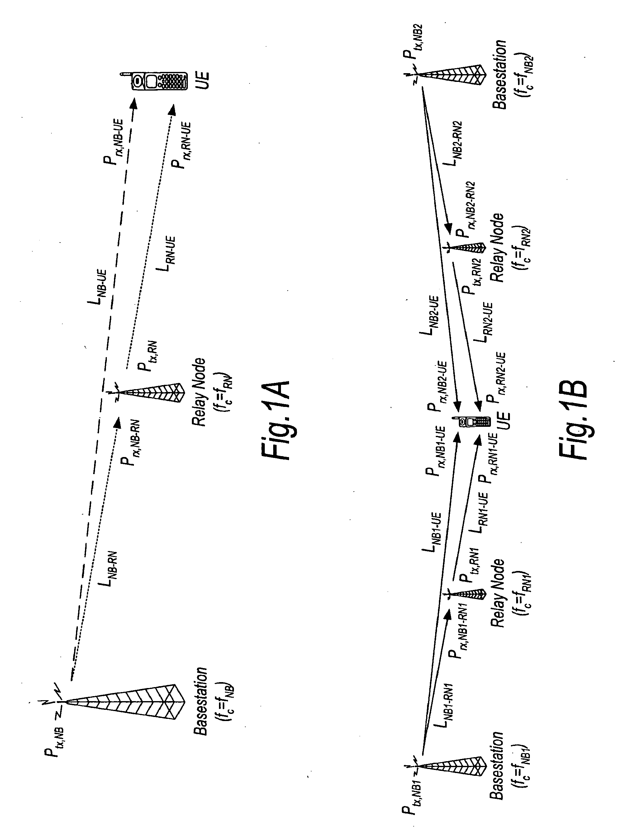
It is known that the occurrence of propagation loss, or “pathloss”, due to the scattering or absorption of a radio communication as it travels through space, causes the strength of a signal to diminish.
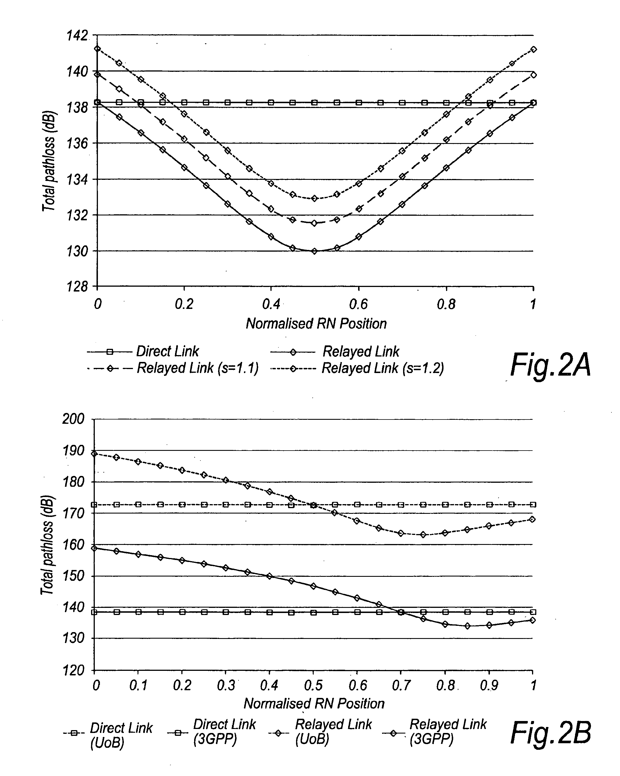
However, simulations carried out to test the applicability of multi-hop communication systems have revealed unexpectedly low gains in throughput of data.

Method used


Image

  • Communication System
  • Communication System
  • Communication System

Examples


second embodiment

[0363]The algorithm described above will manage the case of the propagation loss varying between the RN and NB and the case of the NB modifying its target RSS or SINR. In order to handle the case of the propagation loss varying between the UE and RN and the case that both the target in the NB and the propagation loss between the RN and NB varies, such that no request for change in RN transmit power is generated, an algorithm which implements the fourth aspect of the present invention operates periodically as discussed below (FIG. 13)

[0364]The details of the algorithm are summarised as follows:

Uplink Algorithm 3: Part 2Trigger: Periodically executed in NBAlgorithm InputRequired byOriginSINR at NBNBKnown at NBSINR at RNNBSignalled from RNDestination & SignallingAlgorithm OutputDerivationRequirementChange in UE transmit powerRelativeSignalled to UE via RNchangeBlock on RN power increaseTrue / falsePart 1 of the algorithmtest

[0365]This algorithm is executed periodically in addition to the...

third embodiment

[0413]An example of an algorithm which implements the sixth aspect of the present invention will now be described with reference to FIG. 20, in which the source apparatus comprises a user equipment (UE), the intermediate apparatus comprises a relay node (RN) and the destination apparatus comprises a base station (NB). The present embodiment seeks to attain or maintain a balance between the QoS experienced on the UL communication links (UE-RN and RN-NB) by adjusting the bandwidth allocated to the RN-UE communication link.

[0414]The details of the algorithm are summarised as follows:

Uplink Algorithm 1A&B: Part 1 (Centralised with QoS derived at NB)Trigger: Periodically executed in NBAlgorithm InputRequired byOriginRequest for change inRNChange derived in NB andBW allocation at RNprocessed by RNBlock in increase inRNBlock is set / cleared inBW allocation at RNpart 2 of the algorithmDestination & SignallingAlgorithm OutputDerivationRequirementChange in RN BW allocationRelativeRelative chan...

fourth embodiment

[0416]The algorithm described above will manage the case of the propagation loss varying between the RN and NB and the case of the NB modifying its target QoS. In order to handle the case of the propagation loss varying between the UE and RN and the case that both the target in the NB and the propagation loss between the RN and NB varies, such that no request for change in RN bandwidth allocation is generated, an algorithm which implements the sixth aspect of the present invention operates periodically as discussed below with reference to FIG. 21.

[0417]The details of the algorithm according to the fourth embodiment are summarised as follows:

Uplink Algorithm 1A: Part 2 (Centralised with RN QoS derived at RN)Trigger: Periodically executed in NBAlgorithm InputRequired byOriginQoS at NBNBKnown at NBQoS at RNNBSignalled from RNDestination & SignallingAlgorithm OutputDerivationRequirementChange in UE BW allocationRelativeSignalled to UE via RNchangeBlock on RN BW allocationTrue / falsePart ...


PUM


Abstract

The present application relates to a wireless communication system and related methods and apparatuses for transmitting a signal from a source apparatus to a destination apparatus, via at least one intermediate apparatus. In particular, the present invention relates to techniques which seek to improve the throughput of data in multi-hop communication systems.

Description

CROSS-REFERENCE TO RELATED APPLICATIONS[0001]This application is a divisional of U.S. patent application Ser. No. 11 / 453,055, filed Jun. 15, 2006, which is based upon and claims the benefit of priority from the prior European Patent Application No. 05253783.4, filed on Jun. 17, 2005, the entire contents of which are incorporated herein by reference.FIELD[0002]The present invention relates to a wireless communication system and related methods for transmitting a signal from a source apparatus to a destination apparatus, via at least one intermediate apparatus. In particular, the present invention relates to techniques which seek to improve the throughput of data in multi-hop communication systems.BACKGROUND[0003]It is known that the occurrence of propagation loss, or “pathloss”, due to the scattering or absorption of a radio communication as it travels through space, causes the strength of a signal to diminish. Factors which influence the pathloss between a transmitter and a receiver...

Claims


Application Information

Patent Timeline
IPC IPC(8): H04W72/04H04B17/40
CPCH04B7/2606H04W28/08H04W52/46H04W88/04H04B17/318H04B17/336H04W28/0942H04W28/0983H04W28/18H04W84/18Y02D30/70
Inventor HART, MICHAEL JOHN
Owner FUJITSU LTD
Learn More